High speed electrical connector having improved housing

a high-speed electrical connector and housing technology, applied in the direction of coupling device connection, coupling protective earth/shielding arrangement, two-part coupling device, etc., can solve the problems of hard to fix the contacts in the predetermined position within the insulative housing firmly, and the wafer and the spacer cannot be inserted to the predetermined position

Active Publication Date: 2009-10-01
HON HAI PRECISION IND CO LTD
View PDF10 Cites 39 Cited by
  • Summary
  • Abstract
  • Description
  • Claims
  • Application Information

AI Technical Summary

Benefits of technology

[0009]The spacer is conveniently inserted into the insulative base to form the passageways having open front end and open rear end for easing insertion of the contacts along a back-to-front direction. The spacer and the contacts could be respectively firmly fixed in the predetermined position within the housing, via the convenient ordinal insertion of the spacer and the wafer.

Problems solved by technology

When the engagement between the holes defined on the wafer and corresponding posts formed on the spacer is not reliable, it is hard to insert the wafer and the spacer to the predetermined position.
Therefore, the contacts could not be fixed in the predetermined position within the insulative housing firmly.

Method used


Image

  • High speed electrical connector having improved housing
  • High speed electrical connector having improved housing
  • High speed electrical connector having improved housing

Examples


Embodiment Construction

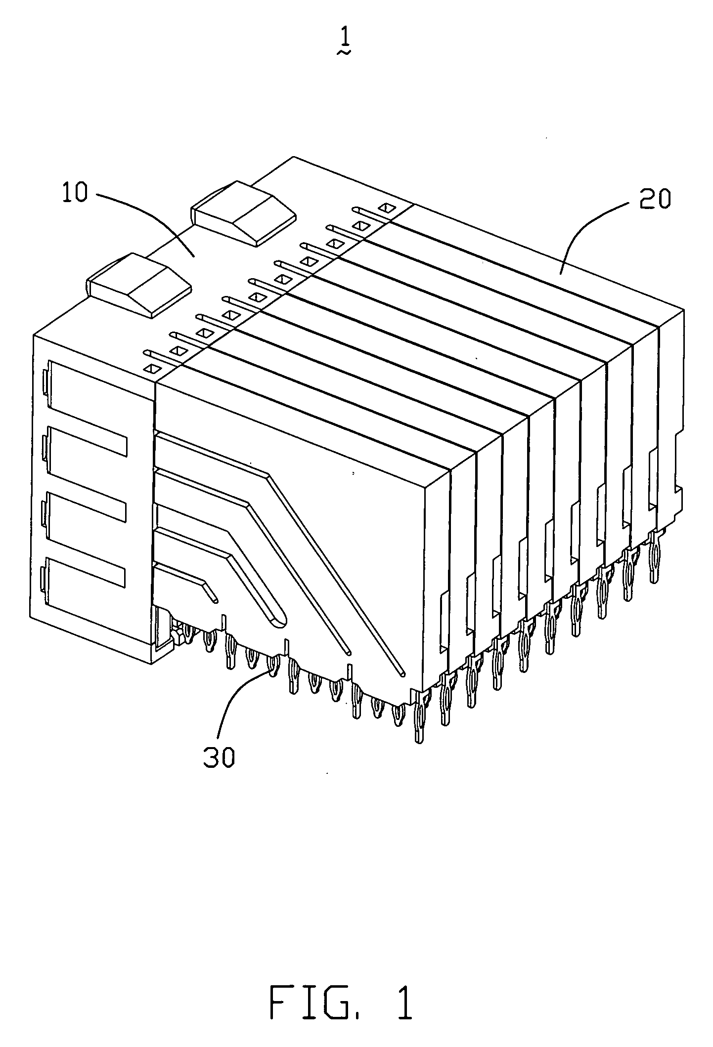
[0016]Reference will now be made to the drawing figures to describe the present invention in detail. FIG. 1 illustrates an electrical connector 1 having an insulative housing 10 and a plurality of wafers 20 mounted on the insulative housing 10. Each wafer 20 has a plurality of contacts 30 and shielding plates 40.

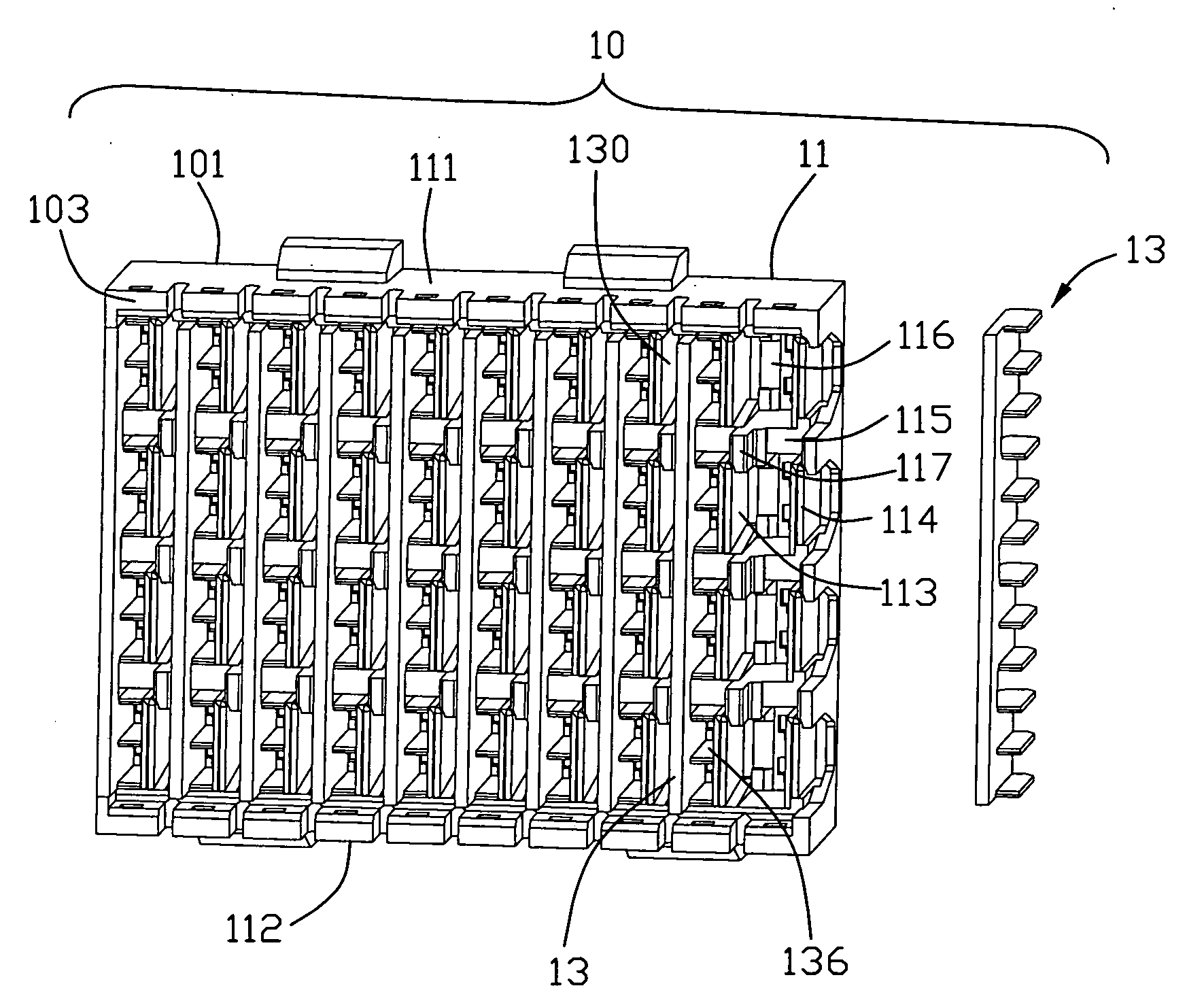
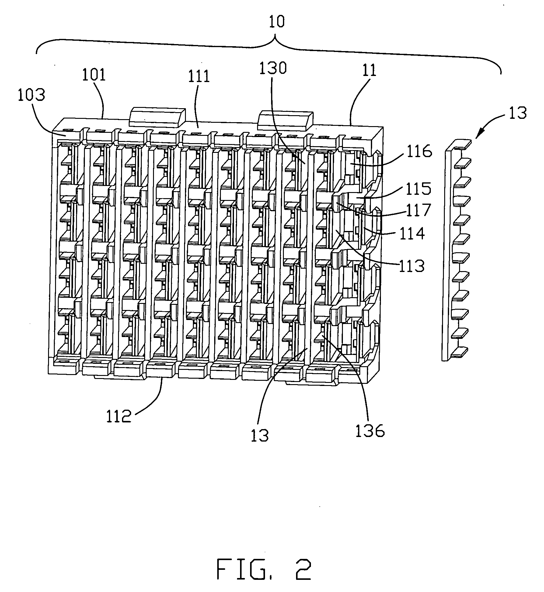
[0017]Referring to FIG. 2, the insulative housing 10 has a mating surface 101 and an opposite mounting surface 103. The insulative housing 10 includes an insulative base 11 and a plurality of spacers 13 mounted on the insulative base 11. The insulative base 11 is of a substantially rectangular cube portion and has a top wall 111 and a bottom wall 112. The insulative base 11 includes a plurality of vertical wall pairs each having a first vertical wall 113 and a second vertical wall 114, and a plurality of horizontal walls 115 perpendicular to the vertical wall pairs 113,114. The insulative base 11 has a plurality of chambers 116 defined by the vertical wall pairs 113,114 and ...


PUM


Abstract

An electrical connector (1) includes a housing (10) and a number of wafers (20). Each wafer has a number of contacts (30) each having a contacting portion (31). The housing includes an insulative base (11) having a number of chambers (115) and a number of spacers (13) mounted on the insulative base. Each spacer includes a main portion (131), and a number of finger-shaped portions (132) formed on the main portion. Each finger-shaped portion has a floor (133) and a number of projecting walls (134, 135) projecting laterally from the floor to form a plurality of passageways. The finger-shaped portion inserted in the chamber of the insulative base. Each passageway has an open front end (137) and an open rear end (138), the contacting portion of the contact inserted into the passageway from the open rear end toward the open front end.

Description

BACKGROUND OF THE INVENTION[0001]1. Field of the Invention[0002]The present invention relates to a high speed electrical connector, and more particularly, to a high speed electrical connector for transmitting high speed signal between mother boards and daughter boards or other electrical components.[0003]2. Description of Related Arts[0004]High speed electrical connector used in High speed systems typically has a great number of contacts, and an insulative housing having a great number of passageways for receiving the contacts. A high speed electrical connector is disclosed in U.S. Pat. No. 6,461,202 issued to Kline on Oct. 8, 2002. The electrical connector includes an insulative housing, a spacer, and a plurality of wafers having a plurality of contacts insert molded on the wafer. The spacer defines thereon a plurality of passageways each having an open side. The wafer should be assembled to the spacer prior to inserting the spacer together with the wafer into the insulative housin...

Claims


Application Information

Patent Timeline
Patent Type & Authority Applications(United States)
IPC IPC(8): H01R13/648H01R13/514
CPCH01R23/688H01R13/514H01R13/6586H01R12/00
Inventor PAN, FENG
Owner HON HAI PRECISION IND CO LTD
Why Eureka
Try Eureka