Linear Engine

a technology of linear engine and transmission line, which is applied in the direction of positive displacement engines, reciprocating piston engines, engine controllers, etc., can solve the problems of double-ended piston gear being actually used, shortening the life of the engine, and undesired inertial load during the engine's operation

Inactive Publication Date: 2009-10-01
BEN SHABAT MORRIS +1
View PDF6 Cites 5 Cited by
  • Summary
  • Abstract
  • Description
  • Claims
  • Application Information

AI Technical Summary

Benefits of technology

[0028]According to the present invention there is provided a linear engine including: (a) a piston; (b) a linear piston leg comprising two opposite cogged edges including: (i) lowering cogs; and (ii) raising cogs; (c) at least one lowering segmental cogwheel, the cogs of which correspond to the cogs of one edge of the linear piston leg; (d) at least one raising segmental cogwheel, the cogs of which correspond to the cogs of one edge of the linear piston leg; and (e) a transmission system connecting said cogwheels to a driveshaft; wherein each of said segmental cogwheels comprising at least two opposi

Problems solved by technology

Furthermore, these engines have additional disadvantages, such as the following: The engine is subject to unnecessary wear within the piston housing, which shortens its life span, seeing as the combustion chambers in these engines are eroded in an oval shape due to the pressure of the crankshaft arm, mostly in the area of ascending.
An obvious disadvantage is that the double-ended piston gear is actually a cogwheel, which is in approximately half of its circumference, cogged, while the other half is not and is smooth.
This structure causes the wheel to be imbalanced around its symmetry axis, causing undesired inertial loads during the

Method used


Image

  • Linear Engine
  • Linear Engine
  • Linear Engine

Examples


Embodiment Construction

[0044]The present invention is of a linear engine.

[0045]The principles and operation of a linear engine according to the present invention may be better understood with reference to the drawings and the accompanying description.

[0046]Before explaining at least one embodiment of the invention in detail, it is to be understood that the invention is not limited in its application to the details of construction and the arrangement of the components set forth in the following description or illustrated in the drawings.

[0047]Unless otherwise defined, all technical and scientific terms used herein have the same meaning as commonly understood by one of ordinary skill in the art to which this invention belongs. The materials, dimensions, methods, and examples provided herein are illustrative only and are not intended to be limiting.[0048]The following list is a legend of the numbering of the application illustrations: 08260 List
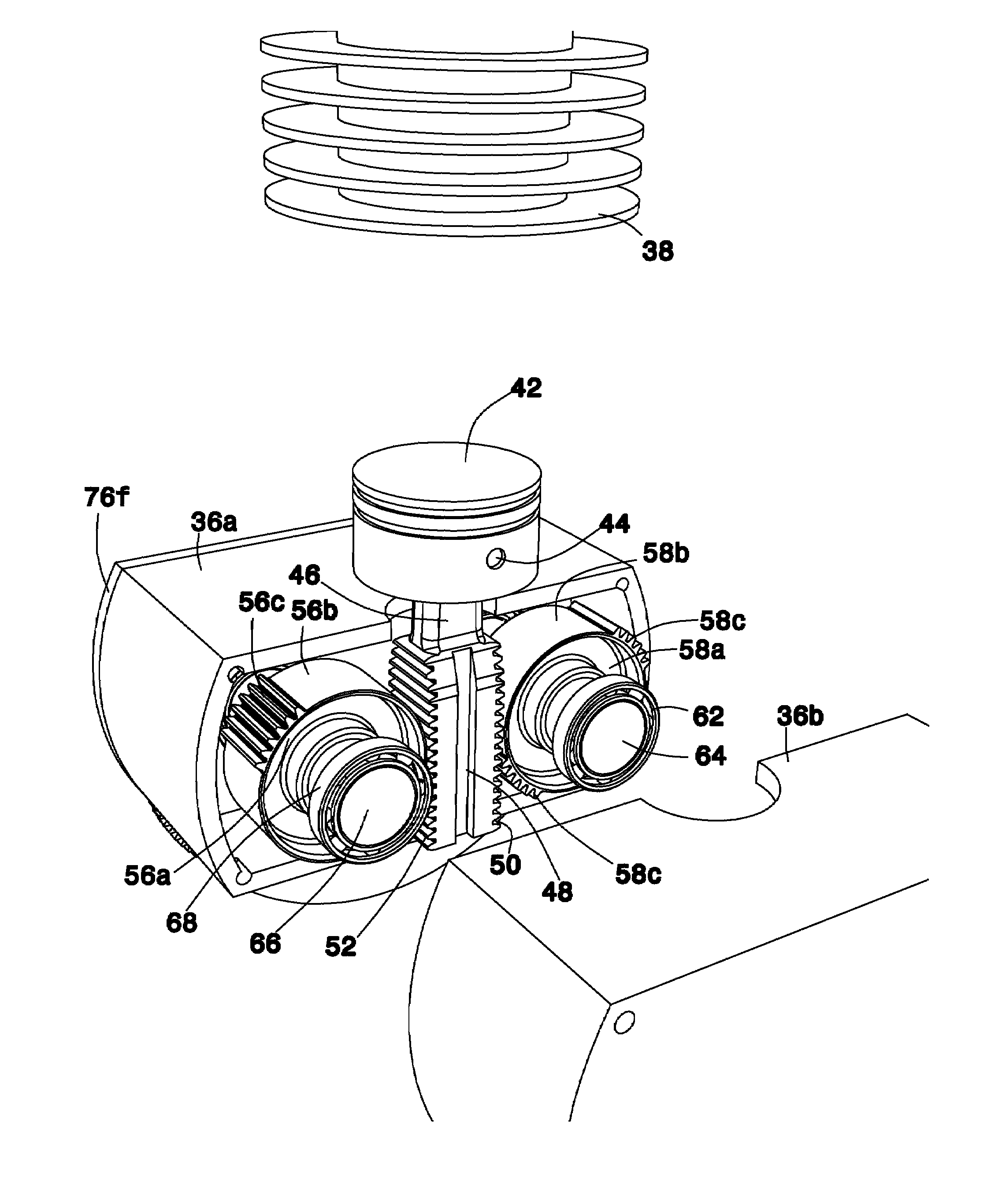
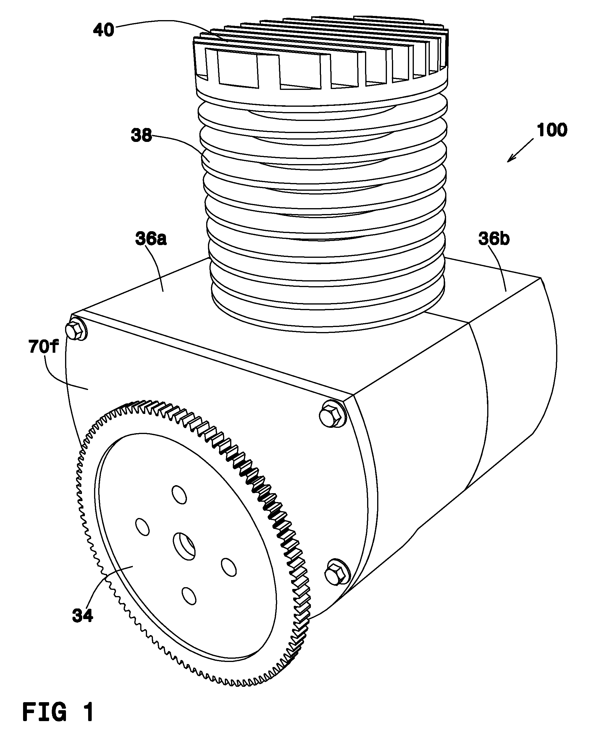
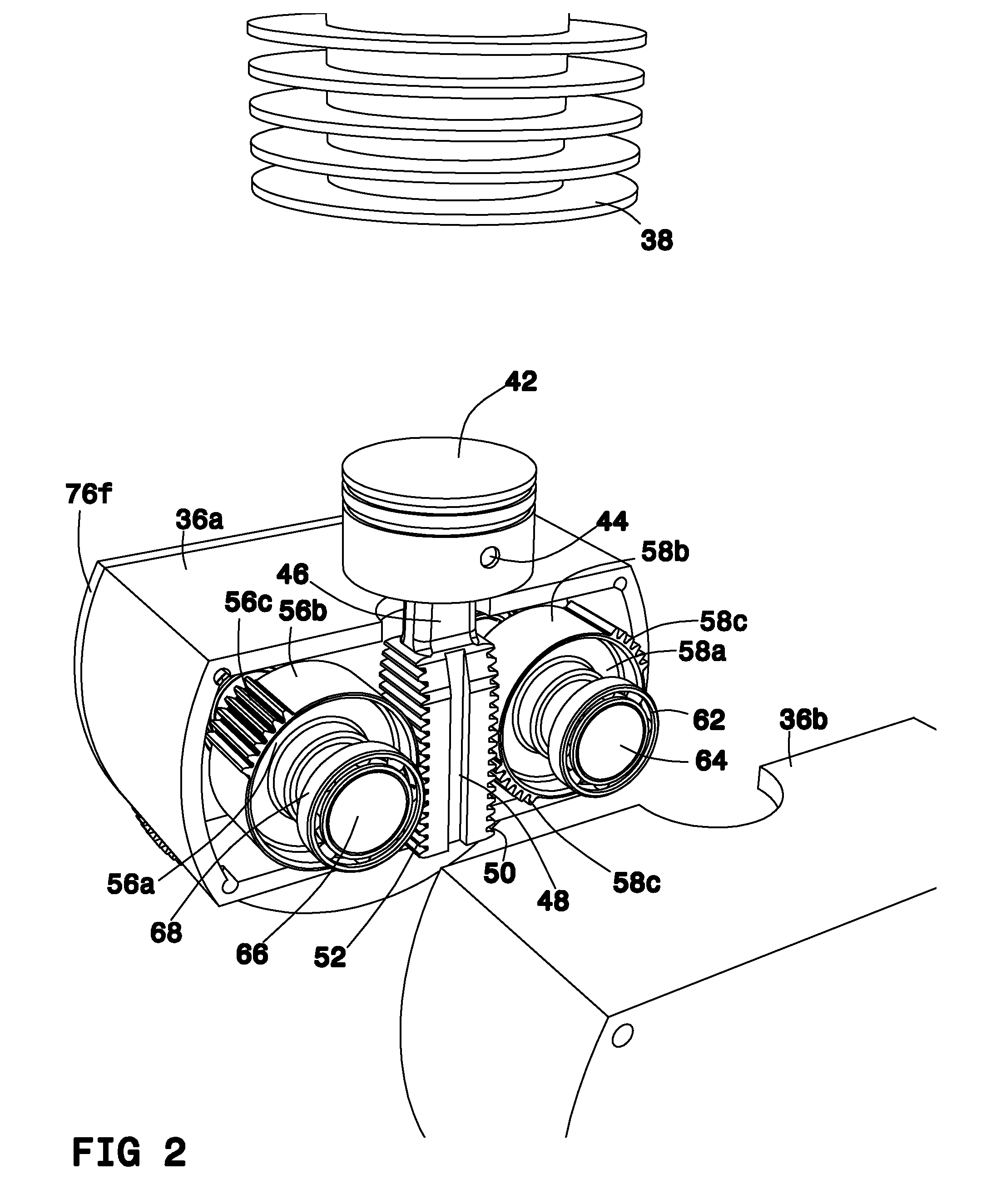
[0049]34 flywheel

[0050]36a transmission housing front wall

[0051]...


PUM


Abstract

In one embodiment, the present invention is directed to a linear engine comprising: a piston; a linear piston leg comprising two opposite cogged edges including: lowering cogs and raising cogs; at least one lowering segmental cogwheel, the cogs of which correspond to said cogs of one edge of said linear piston leg; at least one raising segmental cogwheel, the cogs of which correspond to said cogs of one edge of said linear piston leg; and a transmission system connecting said cogwheels to a driveshaft; wherein each of said segmental cogwheels comprising at least two opposite cogged segments and two opposite cogless segments.

Description

FIELD OF THE INVENTION [0001]The present invention relates to linear transmission of power in an engine and in particular to linear transmission of power in an internal combustion engine or a compressor.BACKGROUND OF THE INVENTION [0002]Most existent internal combustion engines and compressors are operated by pistons which activate piston legs that rotate a driveshaft. Such engines and compressors have a great deal of energy loss, also for the following two reasons:[0003]a. The piston leg's angular movement, which generates energy loss due to its lateral movement component, perpendicular to the longitudinal movement of the piston.[0004]b. Seeing as the engine includes an ex-centric wheel, generates energy loss too.[0005]c. The time interval between each ignition is long due to the ex-centric movement.[0006]Furthermore, these engines have additional disadvantages, such as the following: The engine is subject to unnecessary wear within the piston housing, which shortens its life span,...

Claims


Application Information

Patent Timeline
IPC IPC(8): B60W10/04
CPCF01B9/047Y10T477/688F02B75/32
Inventor BEN-SHABAT, MORRISBEN-SHABAT, JACK
Owner BEN SHABAT MORRIS
Why Eureka
Try Eureka