Efficient Program Instrumentation

a program instrument and program technology, applied in the field of software runtime analysis, can solve the problems of consuming a great deal of memory, slowing down the execution of the program, and affecting the performance of the program, so as to reduce the overhead of instrumentation and slow down the program execution

Inactive Publication Date: 2009-10-01
AVAYA INC
View PDF37 Cites 30 Cited by
  • Summary
  • Abstract
  • Description
  • Claims
  • Application Information

AI Technical Summary

Benefits of technology

[0020]The present invention provides a novel method for determining the number and location of instrumentation probes to be inserted into a program. In particular, the illustrative embodiment advantageously inserts the minimum number of probes that are required to obtain execution coverage for every node in the program's control-flow graph. Moreover, the method requires only one type of node marking and one byte to store information for each probe. The illustrative embodiment thus minimizes instrumentation overhead that can slow down program execution, and is therefore especially well-suited to monitoring Voice over Internet Protocol (VoIP) software.

Problems solved by technology

The introduction of probes into a program, however, adds overhead that can slow down the execution of the program, and thus there is a tradeoff when inserting probes into a program.
However, if there are too many probes, then program runtime performance might suffer appreciably, which is unacceptable in applications such as real-time embedded systems and Voice over Internet Protocol (VoIP).
A key disadvantage of the maximum spanning tree method is that it requires execution counts on each probe, which can consume a great deal of memory.
Moreover, the counter values can grow so large that they impact the original application, and there is no way to reset the counters.
Consequently, the maximum spanning tree method is typically not practical for program monitoring during field operation.

Method used


Image

  • Efficient Program Instrumentation
  • Efficient Program Instrumentation
  • Efficient Program Instrumentation

Examples


Embodiment Construction

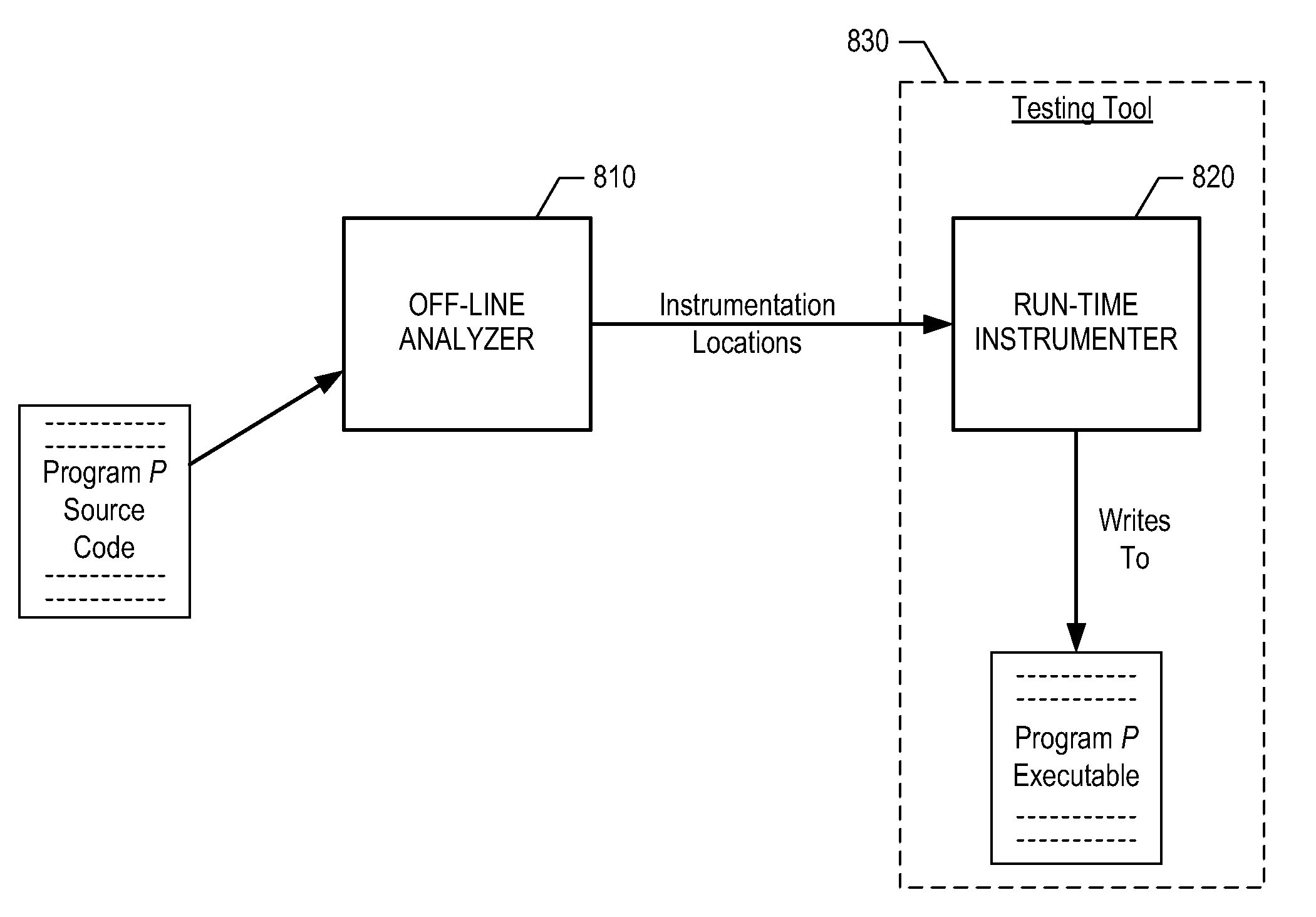
[0039]FIG. 8 depicts the high-level architecture of a first illustrative embodiment of the present invention. As shown in FIG. 8, the first illustrative embodiment comprises off-line analyzer 810, run-time instrumenter 820, and testing / monitoring tool 830, interconnected as shown.

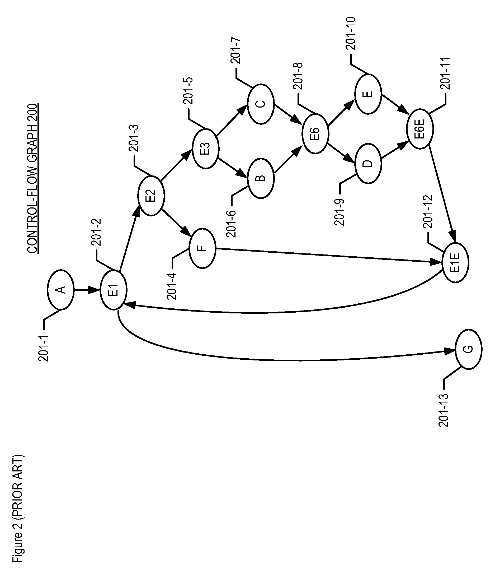
[0040]Off-line analyzer 810 comprises software, or hardware, or a combination of software and hardware capable of determining one or more locations in a program at which an instrumentation probe is to be inserted. The determination of instrumentation locations by off-line analyzer 810—referred to as the Simplified Super Nested Block Method—is described in detail below. The method is first described informally as applied to illustrative control-flow graph 200, and subsequently a formal specification of the method is provided.

[0041]Informal Description of the Simplified Super Nested Block Method

[0042]An informal description of the Simplified Super Nested Block Method as applied to illustrative control-flow gr...


PUM


Abstract

A method for determining the number and location of instrumentation probes to be inserted into a program is disclosed. The method advantageously inserts the minimum number of probes that are required to obtain execution coverage for every node in the program's control-flow graph. In addition, the method requires only type of node marking and one bit to store each probe, and does not require the assignment of weights to arcs or nodes of the control-flow graph. In the illustrative embodiment, the nodes of a control-flow graph are partitioned into non-empty sets, where each non-empty set corresponds to a super nested block of the program.

Description

CROSS-REFERENCE TO RELATED APPLICATIONS[0001]This application is a continuation-in-part of U.S. patent application Ser. No. 12 / 056,026, filed 26 Mar. 2008 (now pending), entitled “Super Nested Block Method to Minimize Coverage Testing Overhead” (Attorney Docket: 630-272us), which is incorporated by reference.FIELD OF THE INVENTION[0002]The present invention relates to run-time analysis of software in general, and, more particularly, to a method of program instrumentation.BACKGROUND OF THE INVENTION[0003]Instrumentation is a technique that can enable engineers to comprehend, monitor, and assess the operation of software. Typically, a program is instrumented by inserting probes at various points in the program, where the probes report a variety of information such as whether certain portions of a program have been reached (referred to as coverage), the number of times that various portions of the program have been executed (referred to as execution counts), how much time is spent in v...

Claims


Application Information

Patent Timeline
Patent Type & Authority Applications(United States)
IPC IPC(8): G06F9/44
CPCG06F11/3676G06F11/3636
Inventor LI, JUAN JENNYWEISS, DAVID MANDEL
Owner AVAYA INC
Why Eureka
Try Eureka