Three-phase faulted circuit indicator

a faulted circuit and indicator technology, applied in the direction of testing circuits, instruments, electric signalling details, etc., can solve the problem of requiring additional work on the part of installers

Active Publication Date: 2009-10-08
SCHWEITZER ENGINEERING LABORATORIES
View PDF58 Cites 48 Cited by
  • Summary
  • Abstract
  • Description
  • Claims
  • Application Information

AI Technical Summary

Benefits of technology

[0007]Accordingly, it is an object of this invention to provide a three-phase faulted circuit indicator that does not require alignment by an installer.

Problems solved by technology

This requires additional work on the part of the installer.
Furthermore, prior-art multi-conductor FCIs only work on a limited range of cable sizes, and also only work on power cables with substantially round conductors.

Method used


Image

  • Three-phase faulted circuit indicator
  • Three-phase faulted circuit indicator
  • Three-phase faulted circuit indicator

Examples


Embodiment Construction

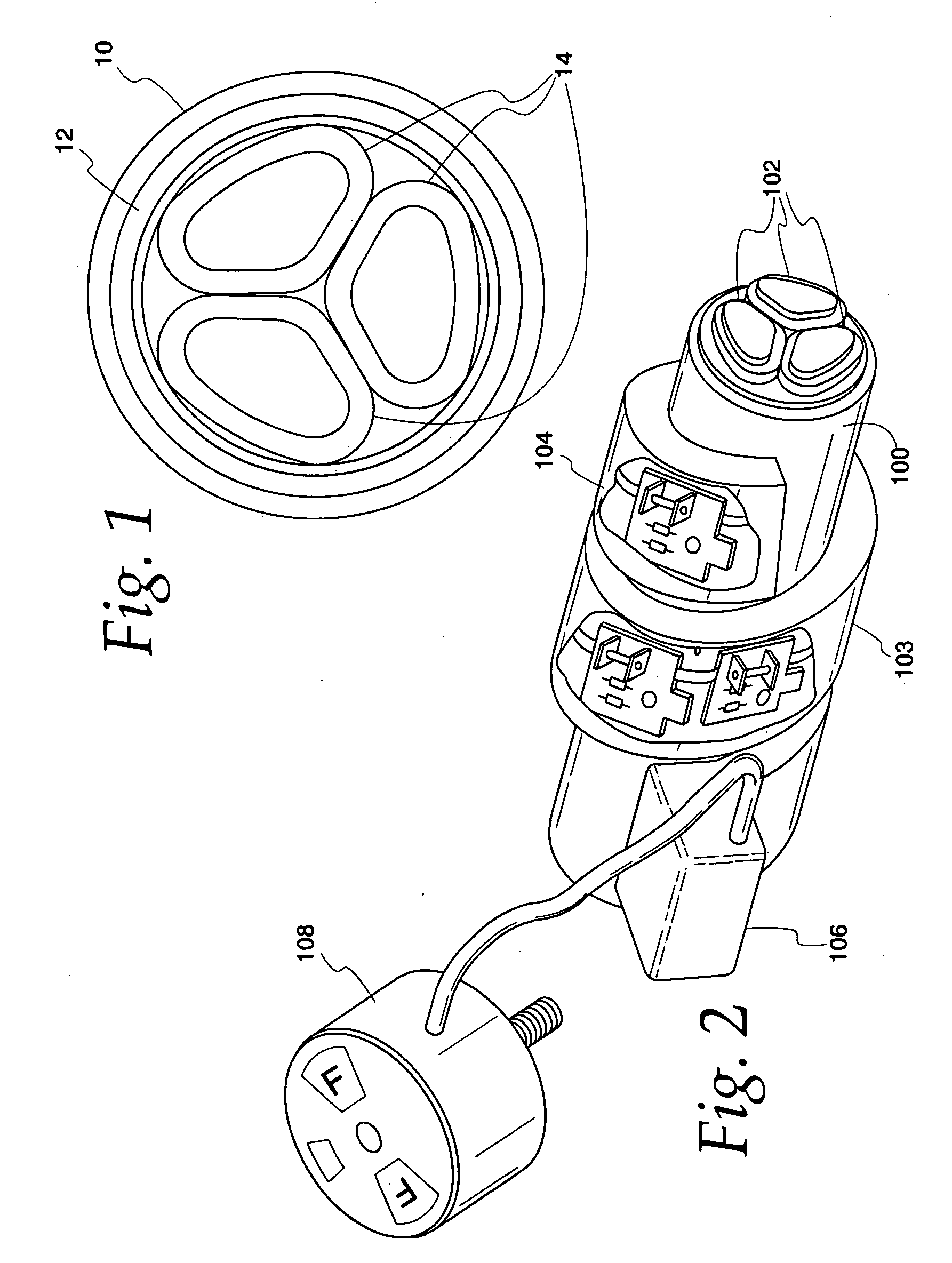
[0044]Turning to the Figures, and to FIG. 1 in particular, a sectional three-phase power cable is depicted. These types of cables are used for power distribution, and tend to comprise an outer sheath 10, as well as one or more layers of insulation 12, which may comprise, for example, a lead sheath of approximately 0.105 inches (0.267 cm) and a metallized paper binder tape. Three conductors 14 are arranged within the power cable. Each conductor will be insulated from the other by, for example, paper insulation of approximately 0.140 inches (0.356 cm) and a zinc alloy shield tape. As each conductor 14 is comprised of numerous smaller wires (not shown), the topography of the conductors 14 is sectional, as opposed to circular. Further, as the three-phase power cable extends longitudinally, the internal conductors 14 may spiral measurably, thereby changing the placement of the conductors relative to one another along the length of the power cable.

[0045]It should be noted that the disclos...


PUM


Abstract

A three-phase faulted circuit indicator adjustable to accommodate a variety of three-phase power cables is disclosed. In one embodiment, faulted circuit indicator comprises a flexible holder that encircles the monitored conductor slightly more than one time. The flexible holder includes a plurality of magnetic sensors for monitoring the current within the internal conductors of the power cable, a logic circuit for determining the occurrence of a fault, and an output device for providing an indication of a fault. In a second embodiment, the faulted circuit indicator comprises a plurality of sensor compartments, each disposed about a central point, and each coupled to two other sensor compartments.

Description

CROSS-REFERENCE TO RELATED APPLICATIONS[0001]This application claims priority under 35 U.S.C. § 119(e) to U.S. Provisional Application 61 / 042,636, entitled “THREE PHASE FAULTED CIRCUIT INDICATOR,” filed on Apr. 4, 2008 on behalf of inventors Edmund O. Schweitzer, III, Laurence V. Feight, Joseph Robert Rauch, and James Manley Duros.FIELD OF THE INVENTION[0002]The present invention relates generally to systems, apparatus, and methods for indicating the presence of a fault in a power transmission or distribution system, and more particularly, to systems, apparatus, and methods for detecting a phase-to-phase or phase-to-ground fault within a multi-conductor power cable.DESCRIPTION OF THE PRIOR ART[0003]Various types of self-powered faulted circuit indicators (“FCIs”) have been constructed for detecting electrical faults in power distribution systems, including clamp-on type fault indicators, which clamp directly over cables in the systems and derive their operating power from inductive ...

Claims


Application Information

Patent Timeline
Patent Type & Authority Applications(United States)
IPC IPC(8): G08B1/08G01R19/00G01R31/00G08B21/00G01R31/50
CPCG01R15/20G01R31/025G01R19/16571G01R1/22G01R31/52G01R31/50
Inventor SCHWEITZER, III, EDMUND O.FEIGHT, LAURENCE V.DUROS, JAMES MANELYRAUCH, JOSEPH ROBERT
Owner SCHWEITZER ENGINEERING LABORATORIES
Why Eureka
Try Eureka