Zoom lens system, interchangeable lens apparatus and camera system
- Summary
- Abstract
- Description
- Claims
- Application Information
AI Technical Summary
Benefits of technology
Problems solved by technology
Method used
Image

Examples
embodiment 1
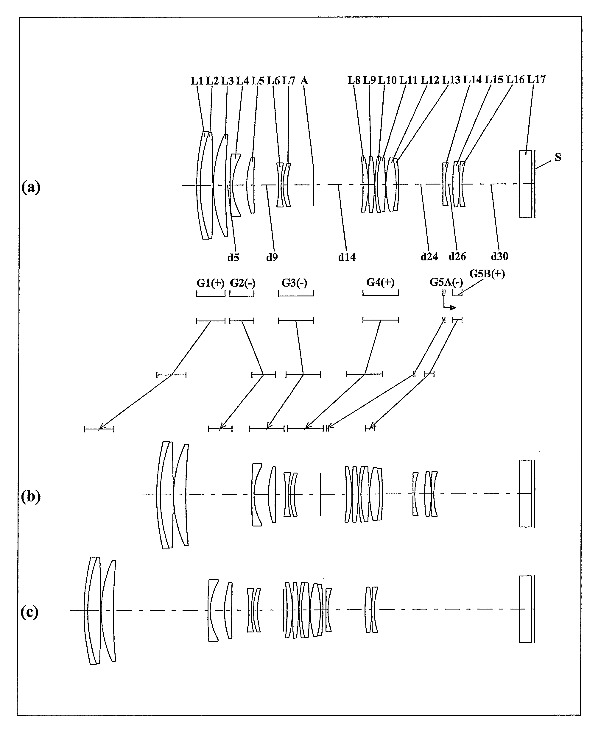
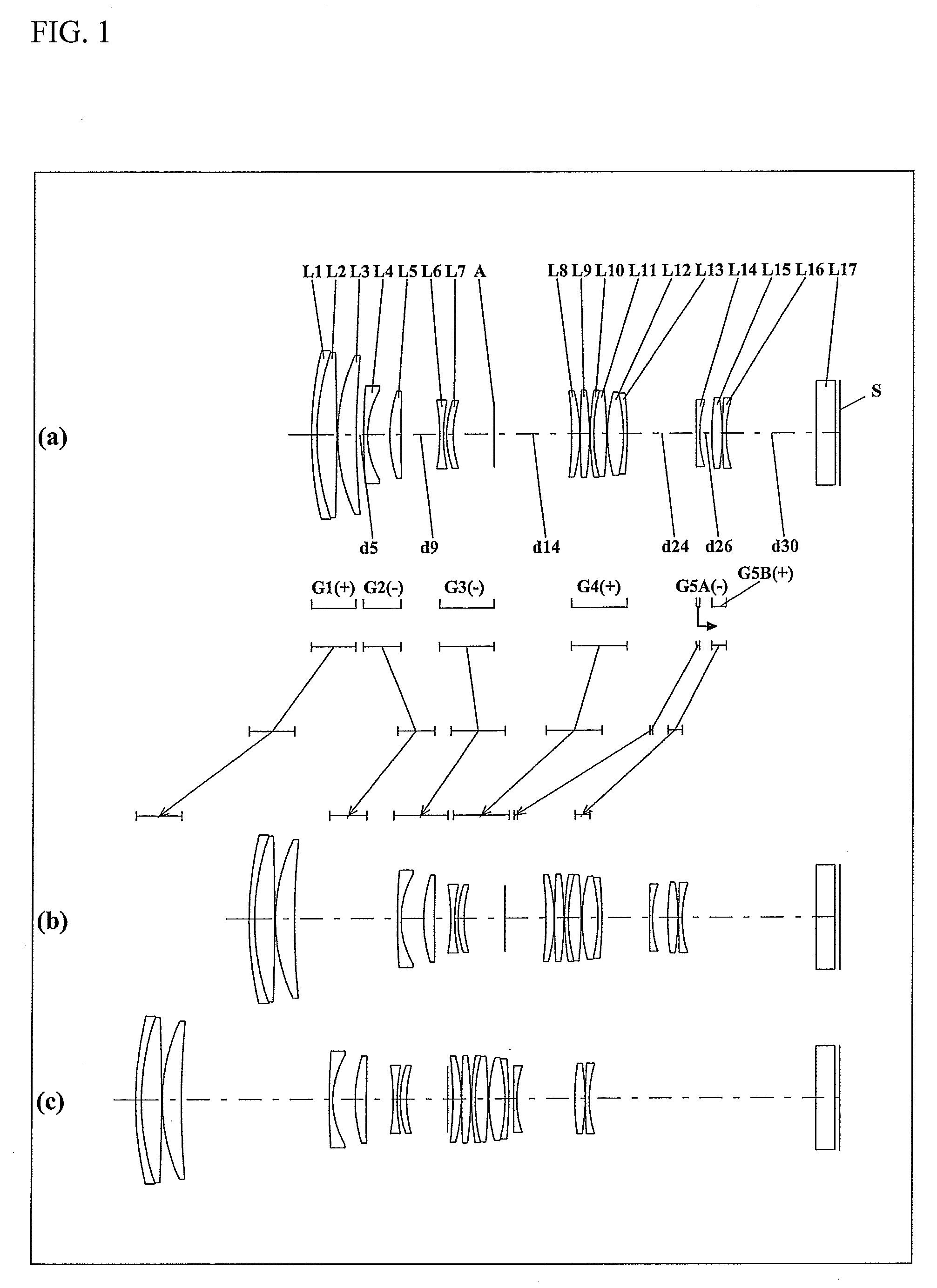
[0052]The zoom lens system according to Embodiment 1, in order from the object side to the image side, comprises a first lens unit G1 having positive optical power, a second lens unit G2 having negative optical power, a third lens unit G3 having negative optical power, a fourth lens unit G4 having positive optical power, a 5A-th lens unit G5A having negative optical power, and a 5B-th lens unit G5B having positive optical power.
[0053]The first lens unit G1, in order from the object side to the image side, comprises: a negative meniscus first lens element L1 with the convex surface facing the object side; a bi-convex second lens element L2; and a positive meniscus third lens element L3 with the convex surface facing the object side. The first lens element L1 and the second lens element L2 are cemented with each other.
[0054]The second lens unit G2, in order from the object side to the image side, comprises: a negative meniscus fourth lens element L4 with the convex surface facing the ...
embodiment 2
[0063]The zoom lens system according to Embodiment 2, in order from the object side to the image side, comprises a first lens unit G1 having positive optical power, a second lens unit G2 having negative optical power, a third lens unit G3 having negative optical power, a fourth lens unit G4 having positive optical power, a fifth lens unit G5 having negative optical power, and a 5B-th lens unit G5B having positive optical power.
[0064]The first lens unit G1, in order from the object side to the image side, comprises: a negative meniscus first lens element L1 with the convex surface facing the object side; a bi-convex second lens element L2; and a positive meniscus third lens element L3 with the convex surface facing the object side. The first lens element L1 and the second lens element L2 are cemented with each other.
[0065]The second lens unit G2, in order from the object side to the image side, comprises a bi-concave fourth lens element L4 and a bi-convex fifth lens element L5.
[0066]...
embodiment 3
[0075]The zoom lens system according to Embodiment 3, in order from the object side to the image side, comprises a first lens unit G1 having positive optical power, a second lens unit G2 having negative optical power, a third lens unit G3 having negative optical power, a fourth lens unit G4 having positive optical power, a 5A-th lens unit G5A having positive optical power, and a 5B-th lens unit G5B having negative optical power.
[0076]The first lens unit G1, in order from the object side to the image side, comprises: a negative meniscus first lens element L1 with the convex surface facing the object side; a positive meniscus second lens element L2 with the convex surface facing the object side; and a positive meniscus third lens element L3 with the convex surface facing the object side. The first lens element L1 and the second lens element L2 are cemented with each other.
[0077]The second lens unit G2, in order from the object side to the image side, comprises a bi-concave fourth lens...
PUM
 Abstract
Description
Claims
Application Information