Light combiner

a combiner and light technology, applied in the field of optical devices, can solve the problems of limited output power, difficult to generate a far-field illumination area with uniform illumination intensity, and difficult to optically couple solid-state light sources with light valves

Active Publication Date: 2009-10-08
TEXAS INSTR INC
View PDF10 Cites 32 Cited by
  • Summary
  • Abstract
  • Description
  • Claims
  • Application Information

AI Technical Summary

Benefits of technology

[0007]In view of the foregoing, disclosed herein is an optical system that comprises at least one optical filter, such as a dichroic filter (e.g. a thin film interference filter),

Problems solved by technology

Despite their recognized superior properties over traditional light sources, solid-state light sources can be difficult to optically couple with light valves in imaging systems for illuminating light valves.
For example, it is difficult to generate a far-field illumination area with uniform illumination intensity at a light valve location using solid-state or narrow-band light sources.
Because a single light source may have limited output power, which may not be sufficient to

Method used


Image

  • Light combiner
  • Light combiner
  • Light combiner

Examples


Embodiment Construction

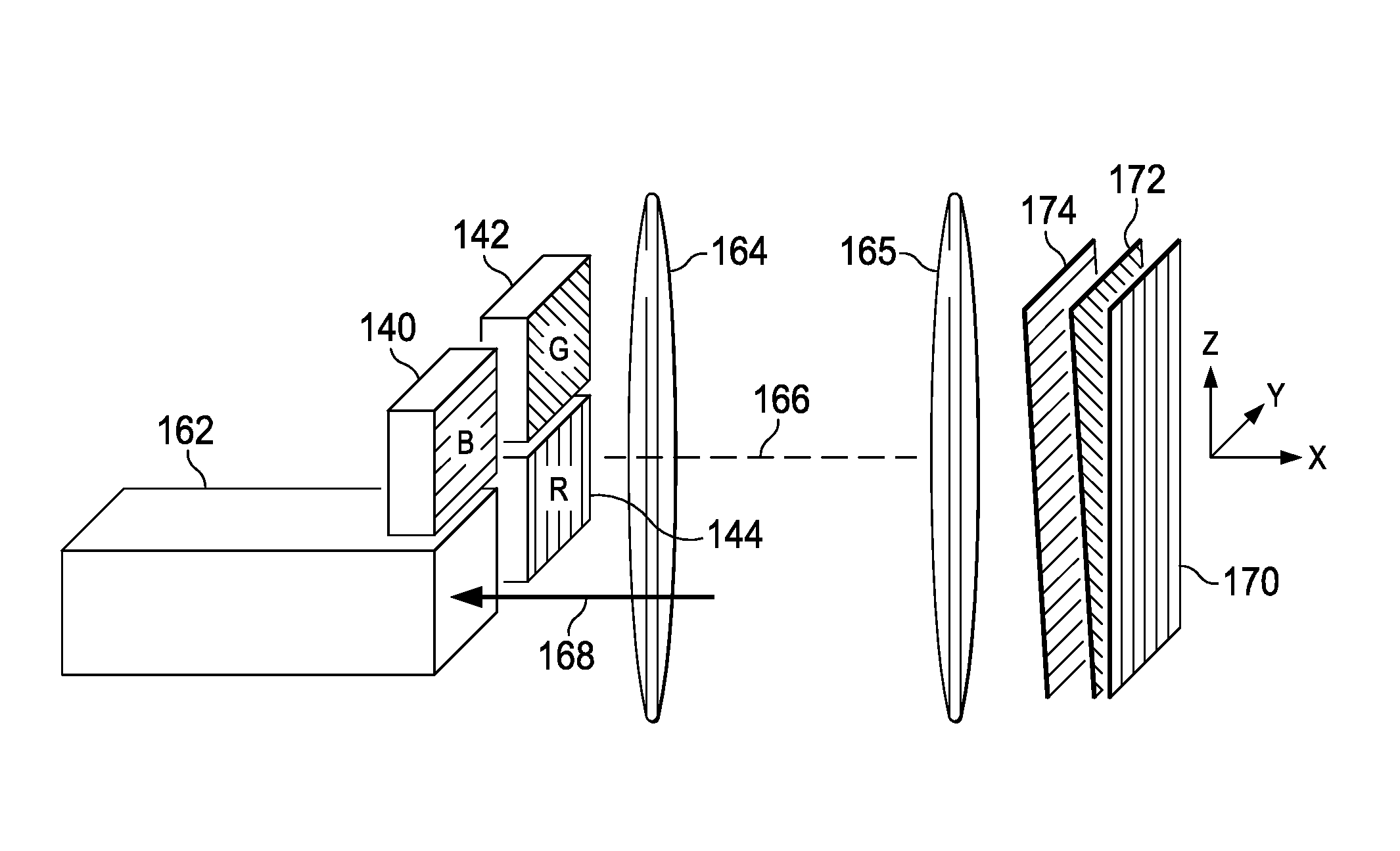
[0038]Disclosed herein is an optical system that comprises at least one optical filter and a reflective surface for directing light from a group of light sources. A reflective surface here can refer to a surface that reflects light of certain polarization or wavelength, such as a mirror, or a second optical filter such as a dichroic filter or reflective polarizer. The reflective surface and the optical filter are typically flat, but they can also be curved or have optical power. In the following, the optical system will be discussed with reference to particular examples. However, it will be appreciated by those skilled in the art that the following discussion is for demonstration purpose, and should not be interpreted as a limitation. Other variations within the scope of this disclosure are also applicable.

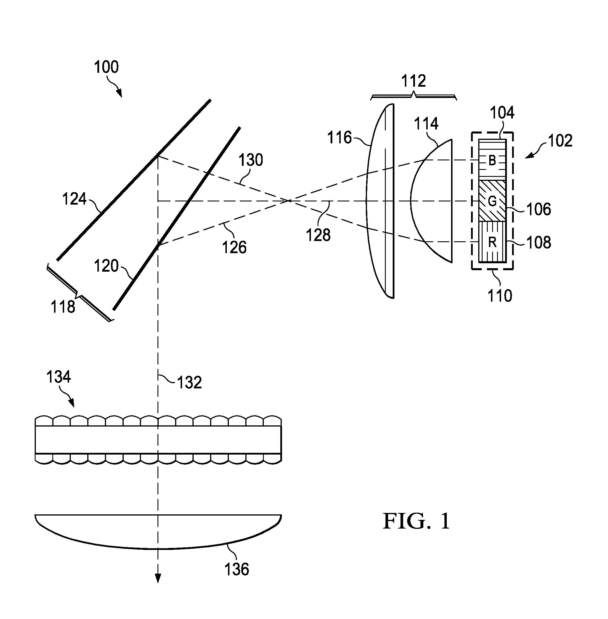
[0039]Referring to the drawings, FIG. 1 is a diagram showing an exemplary optical system of this disclosure. Optical system 100 in this example comprises light source 102, collima...


PUM


Abstract

For combining light from different light sources in a light source, dichroic filters are displaced individually according to the physical arrangement of the light sources such that the reflected light from the dichroic filters is coincident in angle and space.

Description

TECHNICAL FIELD OF THE DISCLOSURE[0001]The technical field of this disclosure relates to the art of optical devices; and more particularly to the art of optical systems for directing illumination light to light valves in imaging systems.BACKGROUND OF THE DISCLOSURE[0002]In recent years, solid-state light sources and other narrow-wavelength-band and / or polarized light sources capable of producing visible light have drawn significant attention as alternative light sources to traditional light sources for use in imaging systems (such as projection systems) due to many advantages, such as compact size, greater durability, longer operating life, and lower power consumption. For example, solid state sources such as LASERs, light-emitting-diodes (LEDs), and pumped non-linear optical crystals are increasingly used in imaging systems, especially imaging systems that employ one or more light valves each of which comprises an array of individually addressable pixels.[0003]Despite their recogni...

Claims


Application Information

Patent Timeline
IPC IPC(8): G02B27/10G02B5/28
CPCG02B27/148G02B27/1033
Inventor HUIBERS, ANDREW GERRITTGRASSER, REGIS
Owner TEXAS INSTR INC
Why Eureka
Try Eureka