Color recapture for display systems

a display system and color recapture technology, applied in the field of display systems, can solve the problems of increasing the cost, size and weight of the display system, generating additional heat that must be dissipated by larger light sources, and failing to detect pulsing, etc., to achieve the effect of three modulator panel system efficiencies, higher efficiency, and improved illumination efficiency

Inactive Publication Date: 2006-06-27
TEXAS INSTR INC
View PDF41 Cites 23 Cited by
  • Summary
  • Abstract
  • Description
  • Claims
  • Application Information

AI Technical Summary

Benefits of technology

[0018]The disclosed invention provides the technical advantage of much higher illumination efficiency. Since all color components of the beam of light are used at all times, the disclosed system and method achieve three modulator panel system efficiencies using only a single modulator panel. The higher efficiency enables the use of lower cost light sources that have longer operational lives and produce less heat. The apparatus required to implement the disclosed invention is much less costly than the optics and modulator panels required to implement a three panel display solution. Because less heat is generated, the overall display system volume will decrease since there is a reduced need for cooling fans and air ducts.

Problems solved by technology

Increasing the light source, however, also increases the cost, size, and weight of the display system.
Additionally, larger light sources generate additional heat that must be dissipated by the display.
If the pixel is pulsed quickly enough, the human eye will accurately measure the average intensity of the pixel, but will fail to detect the pulsing.
The disadvantage of the three-modulator display system is the cost of the three modulators and the complex optics required both to split the white light beam from the light source into three primary color light beams and to recombine the modulated primary color light beams.
The disadvantage of the single-modulator sequential color display systems is its low image brightness.
Thus, a sequential color display system, while generally less expensive than the three-modulator display system, makes very inefficient use of the light produced by the light source.
The lost light not only reduces the brightness of the image produced by the display system, discarding the light creates several problems for the display system.
The heat must be dissipated by using larger fans, which in turn increase the noise produced by the display system and increase the size of the display system.

Method used


Image

  • Color recapture for display systems
  • Color recapture for display systems
  • Color recapture for display systems

Examples


Embodiment Construction

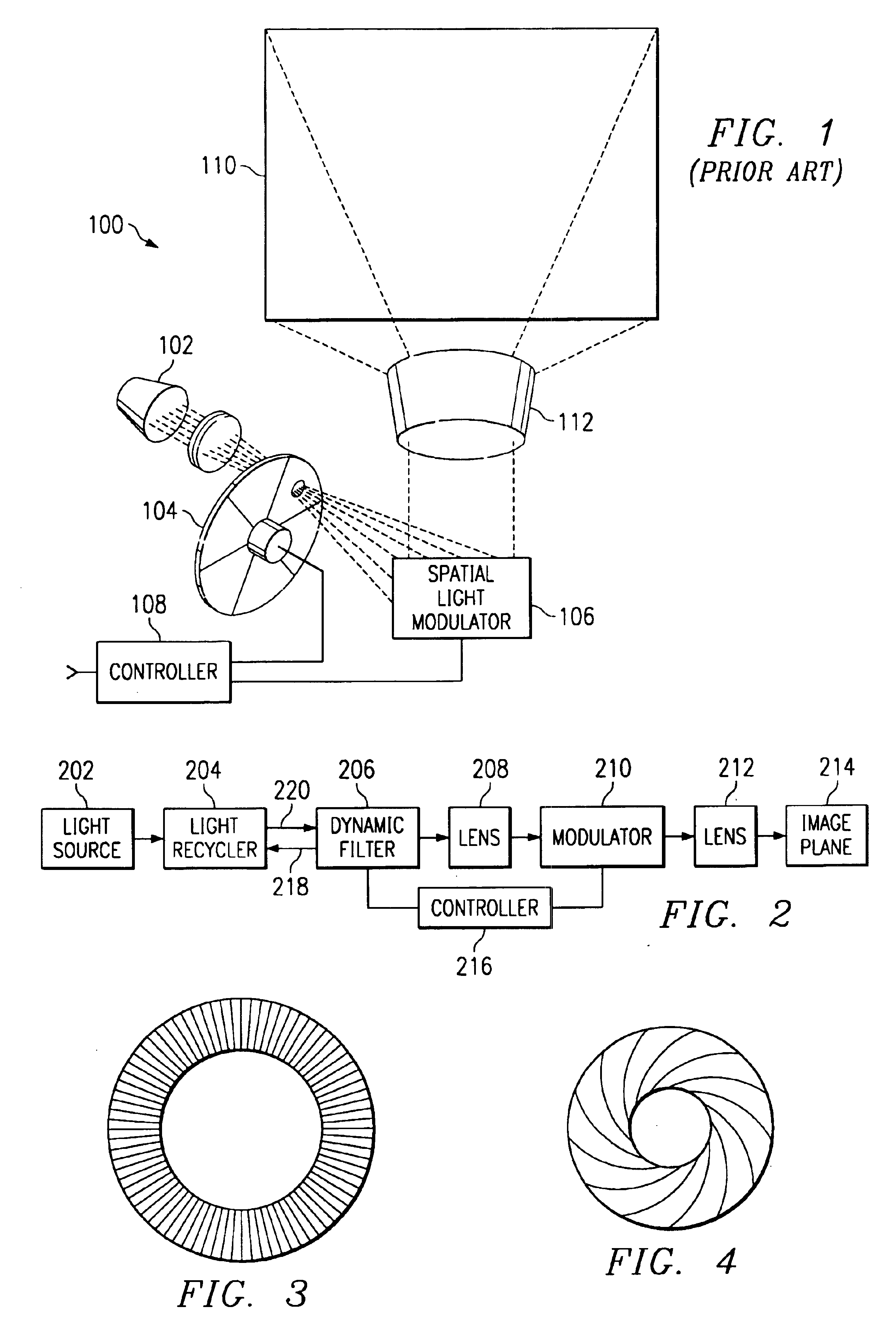
[0039]A new optical system and method have been developed that dramatically improve the optical efficiency of sequential color display systems. The system uses a sequential color concept called falling raster or scrolling color in which the illumination beam laterally changes color. The light rejected by the sequential filters is recycled, that is collected and presented to the filter again, increasing the efficiency of the system. Since more than one color is being displayed at a given time, light rejected by one filter segment can pass through another filter segment if it is successfully routed to another proper filter segment.

[0040]FIG. 1 is a perspective view of a sequential color display system 100. In the display system 100 of FIG. 1, light from source 102 is focused onto a spinning color wheel 104. The spinning color wheel 104 creates of beam of light that changes from one primary color to the next in rapid sequence. The primary colored beam of light impinges a spatial light ...


PUM


Abstract

A sequential color display system using a white light source to create a full color image projected onto an image plane. A dynamic filter, typically a series of moving dichroic filters, generates a series of primary colored light beams that are swept across the surface of a spatial light modulator. Typically all three primary colors are produced simultaneously by the dynamic filter. The illuminated portion of the dynamic filter is imaged onto the modulator and controller provides appropriate image data for each portion of the modulator in synchronization with the sweep of the primary color bands across the modulator surface. The primary color bands are modulated by the spatial light modulator and the modulated light is focused by lens onto the image plane. The viewer integrates the light arriving at each portion of the image plane over a frame period to provide the perception of a full-color image.

Description

CROSS-REFERENCE TO RELATED APPLICATIONS[0001]This application is a Divisional of application Ser. No. 09 / 705,467, filed 3 Nov. 2000 now U.S. Pat. No. 6,771,325 and issued 3 Aug. 2004 which claims priority under 35 U.S.C. § 119(e)(1) of Provisional Application No. 60 / 173,640, filed 30 Dec. 1999 and Provisional Application 60 / 163,866 filed 5 Nov. 1999.[0002]The following patents and / or commonly assigned patent applications hereby are incorporated herein by reference:[0003]Patent No.Filing DateIssue DateTitle5,192,946May 30, 1991Mar. 9, 1993Digitized Color VideoDisplay System5,448,314Jan. 7, 1994Sep. 5, 1995Method and Apparatusfor SequentialColor Imaging5,592,188Jan. 4, 1995Jan. 7, 1997Method And SystemFor AccentuatingIntense White DisplayAreas In SequentialDMD Video Systems5,612,753Jan. 27, 1995Mar. 18, 1997Full-Color ProjectionDisplay System UsingTwo Light Modulators5,760,976Apr. 15, 1997Jun. 2, 1998Kinematic IntegratingOptic Mount6,642,969Dec. 21, 2000Nov. 4, 2003Color Wheel for aFa...

Claims


Application Information

Patent Timeline
Patent Type & Authority Patents(United States)
IPC IPC(8): G03B21/00G02B21/14G03B21/28H04N5/74H04N9/12G03B21/14H04N5/64H04N9/31
CPCG03B21/14H04N9/3117H04N9/3197H04N9/3152H04N9/315G03B21/2066G03B21/208
Inventor DEWALD, DUANE S.PENN, STEVEN M.DAVIS, MICHAEL T.
Owner TEXAS INSTR INC
Why Eureka
Try Eureka