LED light apparatus and methodology

a technology of led light and led light, applied in the direction of lighting applications, lighting support devices, light source combinations, etc., can solve the problems of complete waste of energy, and achieve the effect of convenient operation

Inactive Publication Date: 2006-02-28
WATERS RYAN
View PDF23 Cites 24 Cited by
  • Summary
  • Abstract
  • Description
  • Claims
  • Application Information

AI Technical Summary

Benefits of technology

[0019]Another object of the present invention is to provide a novel LED light apparatus and methodology th

Problems solved by technology

This is completely wasted energy, because the majority o

Method used


Image

  • LED light apparatus and methodology
  • LED light apparatus and methodology
  • LED light apparatus and methodology

Examples


Embodiment Construction

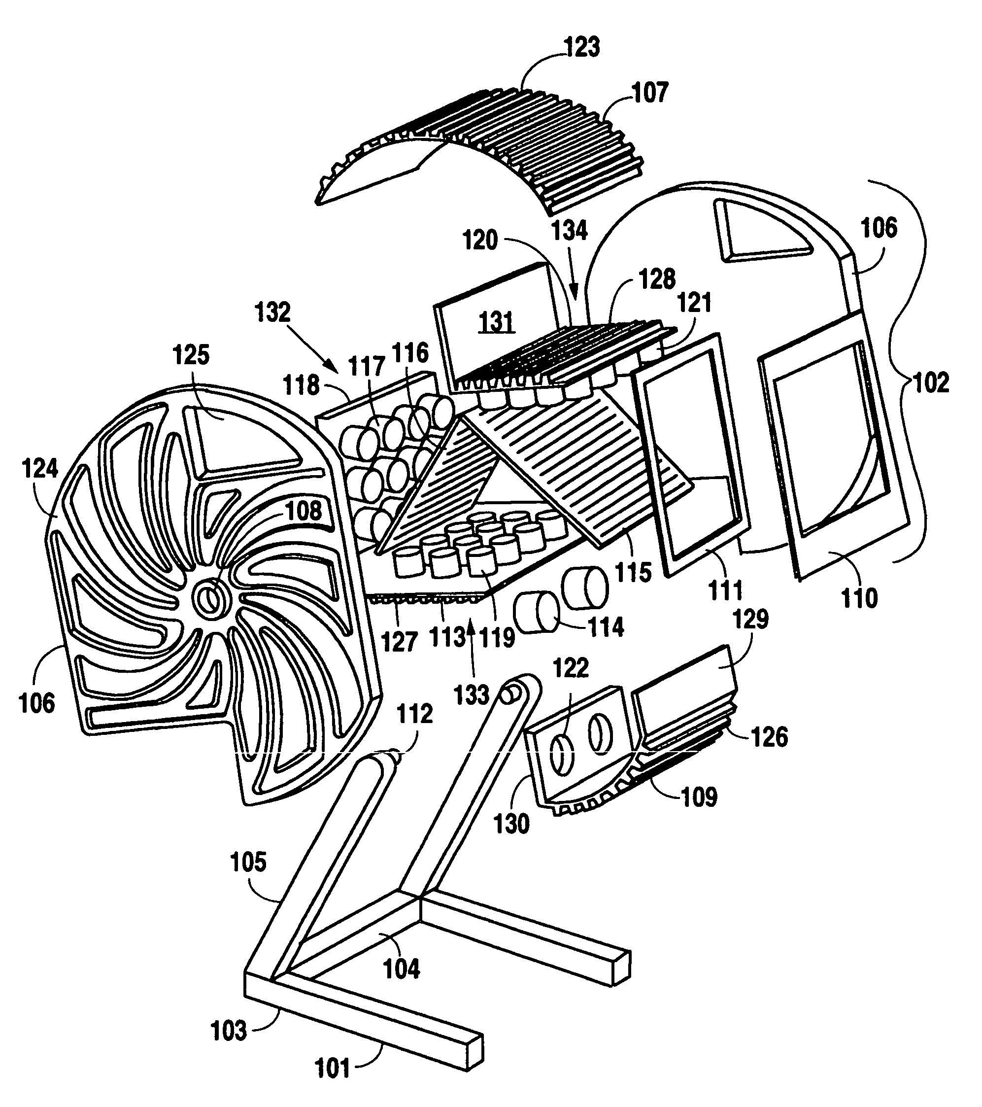
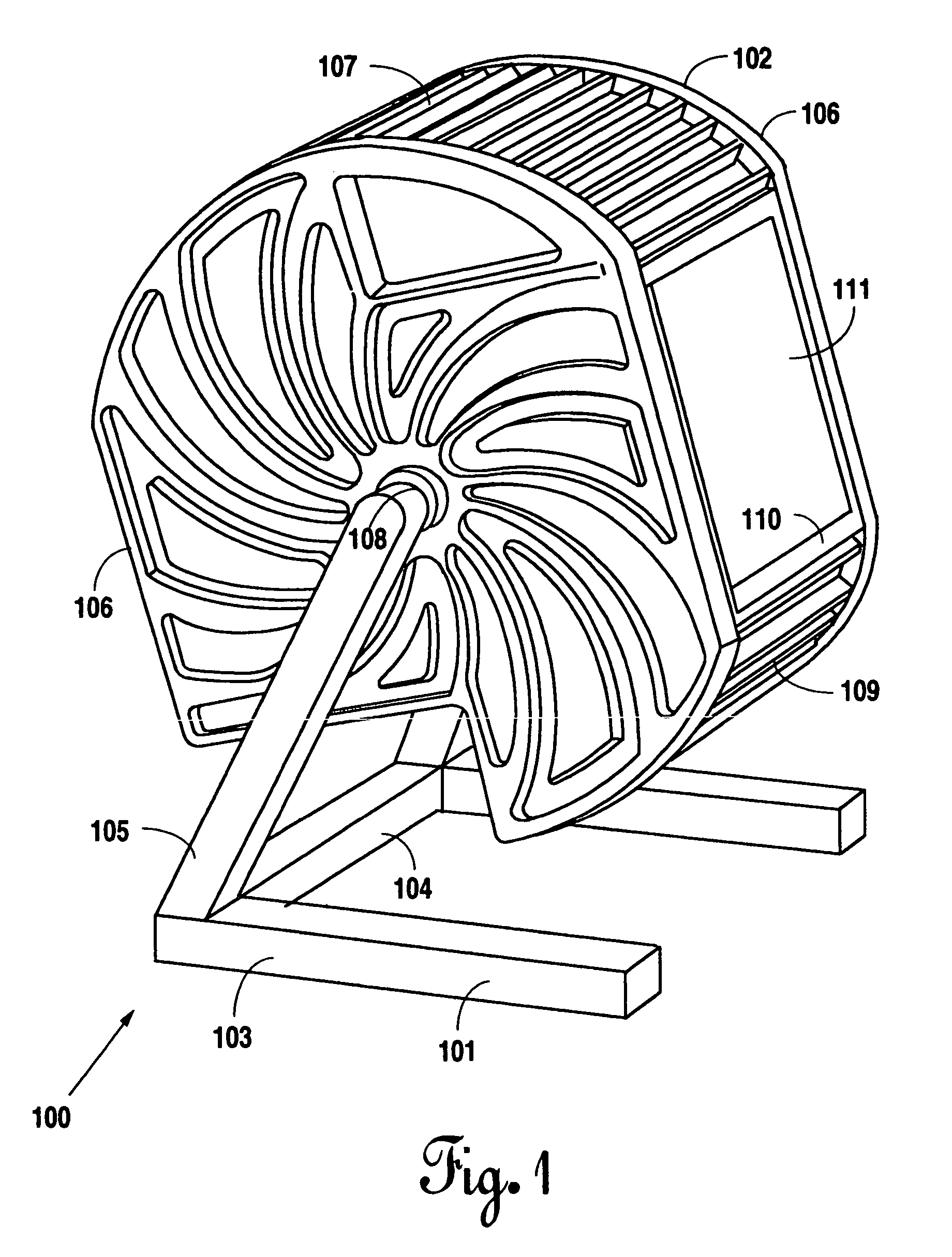
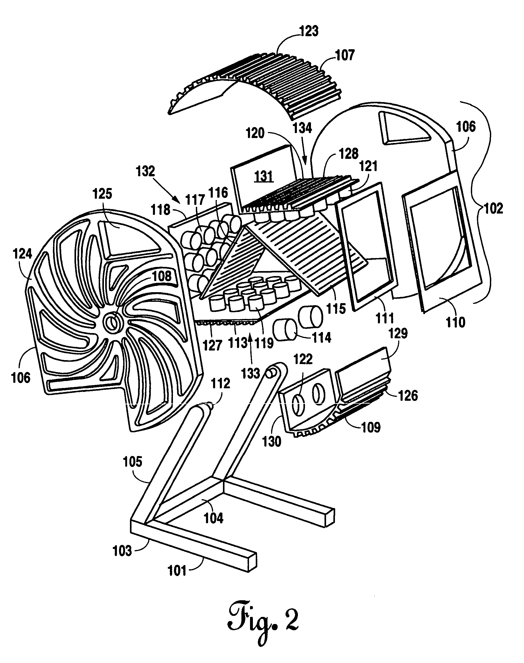
[0042]FIG. 1 is a perspective view of the preferred embodiment of the present LED light apparatus 100. The apparatus 100 has a base 101 and a housing 102. Base 101 can be assembled in many obvious designs to functionally support housing 102. In instances where it is necessary to secure the present apparatus 100 to the wall or ceiling, an appropriate mounting structure (not shown) can be attached to the top or back of the present invention effectively eliminating the need for the base 101. In the preferred embodiment, base 101 has two horizontal legs 103, each connected at the side of one end to opposing ends of connecting leg 104. At the end of horizontal legs 103 that incorporate connecting leg 104, there is attached at the top of each of horizontal legs 103 an angled leg 105 that extends upward to connect to housing 102 at base connection opening 108. Housing 102 as shown has two side heat sinks 106. Side heat sinks 106 are joined at their top portions with upper heat sink 107. Th...


PUM


Abstract

An LED light apparatus and methodology that can produce a collinear beam of light. The apparatus has a housing with three sets of LED light assemblies each having several LED lights of the same color, being red, blue or green. A dichroic bandpass filter and a dichroic notch filter are incorporated along with a power supply. In one embodiment both filters intersect forming an x-pattern. Red light passes through both filters. The resulting light from the bandpass filter combines with blue light and passes through the notch filter. This combined light stream then combines with green light to form a collinear beam of white or colored light. The resulting light from the red light passing through the notch filter combines with green light and passes through the bandpass filter. This combined light stream then combines with the blue light to form a collinear beam of white or colored light.

Description

[0001]This application is a continuation in part application claiming priority to U.S. patent application Ser. No. 10 / 374,949 filed Feb. 25, 2003.BACKGROUND OF THE INVENTION[0002]1. Field of the Invention[0003]Applicant's invention relates to an LED light apparatus and methodology. More particularly the present invention relates to an LED light apparatus and methodology that can produce a collinear beam of white or colored light.[0004]2. Background Information[0005]An LED is a light emitting diode. A diode is a semiconductor i.e. a material with a varying ability to conduct electrical current. A semiconductor with extra electrons is referred to as N-type material and in this material free electrons move from a negatively charged area to a positively charged area. In contrast, a semiconductor with extra holes is a P-type material. Electrons in the P-type material jump from hole to hole moving from a negatively charged area to a positively charged area. A diode is composed of a sectio...

Claims


Application Information

Patent Timeline
IPC IPC(8): F21V13/00F21S8/00F21V9/40F21V15/01F21V21/06F21V21/15F21V21/30F21V29/00
CPCF21V9/10F21V29/83F21V21/15F21V29/71F21V29/74F21V29/75F21V29/76F21V29/77F21V21/06F21V21/30F21V29/004F21W2131/406F21Y2101/02F21Y2113/005F21V15/01F21V29/507F21V29/54F21Y2105/16F21Y2113/13F21Y2115/10F21V9/40
Inventor WATERS, RYAN
Owner WATERS RYAN
Why Eureka
Try Eureka