
Image forming apparatus

Inactive Publication Date: 2009-10-08
CANON KK
View PDF4 Cites 7 Cited by
  • Summary
  • Abstract
  • Description
  • Claims
  • Application Information

AI Technical Summary

Benefits of technology

[0013]In order to resolve the above problems, the present invention provides a technology for generating an AC bias used for detection of the remaining amount of toner by an electrostatic-capacitance detection method in a smaller configuration and at a lower cost.

Problems solved by technology

However, since it is necessary to provide the multiple circuit components in such a configuration of the power supply, it is difficult to reduce the size of the power supply.
Furthermore, the provision of the high-voltage power supply for detection of the remaining amount of toner causes an increase of the cost of the image forming apparatus.

Method used


Image

  • Image forming apparatus
  • Image forming apparatus
  • Image forming apparatus

Examples


Embodiment Construction

[0034]Exemplary embodiments of the present invention will herein be described in detail with reference to the attached drawings.

[0035]An mage forming apparatus according to an exemplary embodiment of the present invention will be described in detail.

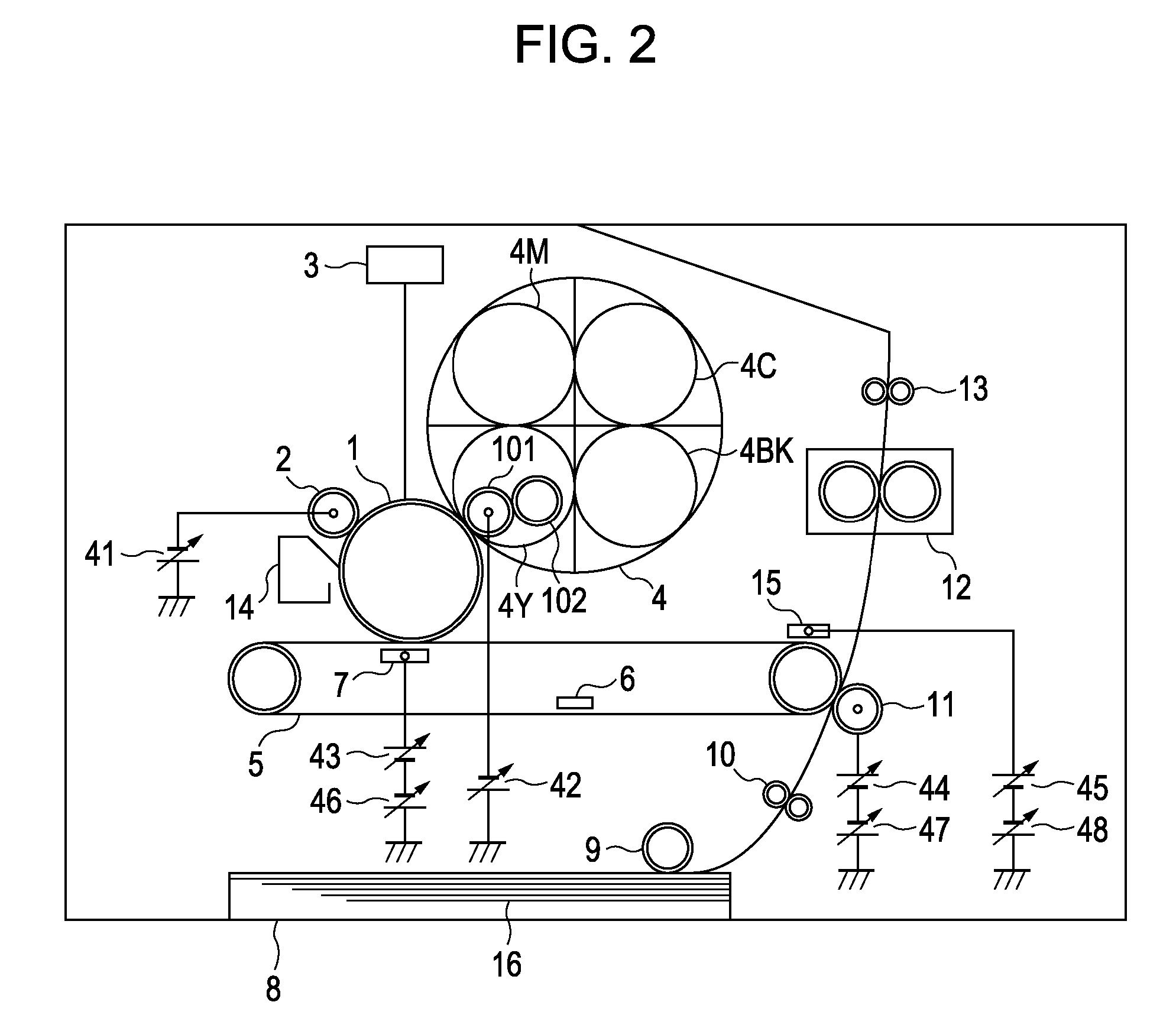
[0036]FIG. 2 schematically shows an example of the configuration of the image forming apparatus using an electrophotographic process applicable to the embodiments of the present invention. In the exemplary embodiments of the present invention, toner is used as the developer, a toner container is the container of the developer, a developing roller 101 is a developer carrier, and a toner image is a developer image. The image forming apparatus includes a photosensitive drum 1 that is an image bearing member. When an image formation operation is started, a charging high-voltage power supply 41 applies a DC negative bias to a charging roller 2 serving as a charging unit to uniformly charge the surface of the photosensitive drum 1. Next, a top...


PUM


Abstract

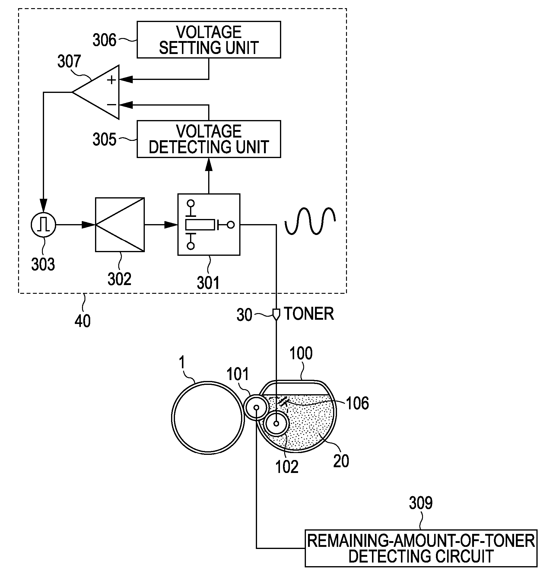
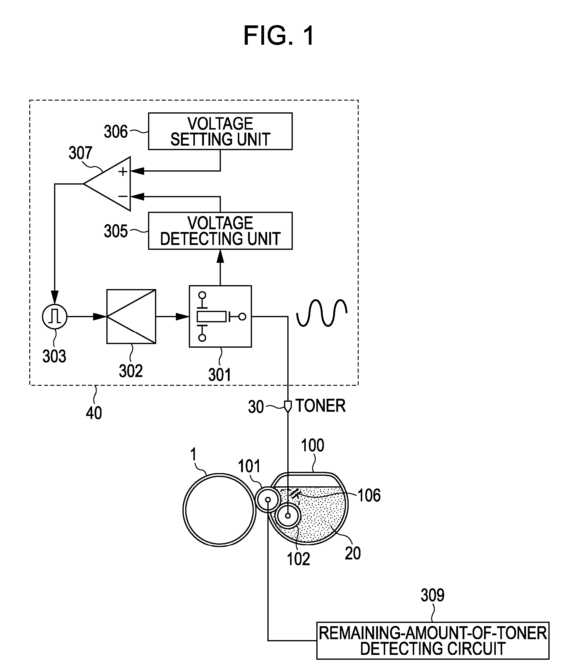
An image forming apparatus includes an alternating-current high-voltage power supply generating an alternating-current bias for detection of the remaining amount of toner. The alternating-current high-voltage power supply includes a piezoelectric transformer, a piezoelectric-transformer driving unit, a piezoelectric-transformer driving-signal generating unit, a voltage detecting unit, a voltage setting unit, and an controlling unit that feeds back a difference signal between a detection level signal supplied from a detection signal detecting unit and a setting signal supplied from the voltage setting unit to the piezoelectric-transformer driving-signal generating unit to control an output voltage from the piezoelectric-transformer.

Description

BACKGROUND OF THE INVENTION[0001]1. Field of the Invention[0002]The present invention relates to an image forming apparatus adopting a technology for detecting the remaining amount of toner.[0003]2. Description of the Related Art[0004]Electrostatic-capacitance detection methods are in widespread use as mechanisms for detecting the remaining amounts of toner in image forming apparatuses using electrophotographic processes. Such electrostatic-capacitance detection methods are disclosed in, for example, Japanese Patent Laid-Open No. 8-44184.[0005]FIGS. 14 and 15 schematically show examples of the configurations of mechanisms for detecting the remaining amount of developer by the electrostatic-capacitance detection method. Toner is used as the developer in the example in FIGS. 14 and 15. A toner container 100 is a container of the developer, and a developing roller 101 is a developer carrier that is provided in the container of the developer and carries and conveys the developer. Referr...

Claims


Application Information

Patent Timeline
IPC IPC(8): G03G15/06G03G15/08G03G15/16
CPCG03G15/5004G03G15/086G03G15/0856G03G2215/0634
Inventor HOTOGI, TATSUYAMATSUO, SHIMPEI
Owner CANON KK
Learn More