Apparatus and method for beamforming in a multiantenna multiuser communication system

a multi-user communication system and apparatus technology, applied in electrical equipment, radio transmission, substation equipment, etc., can solve problems such as performance degradation, signal transmission delay by transmission devices, and performance degradation

Inactive Publication Date: 2009-10-08
SAMSUNG ELECTRONICS CO LTD +1
View PDF2 Cites 13 Cited by
  • Summary
  • Abstract
  • Description
  • Claims
  • Application Information

AI Technical Summary

Benefits of technology

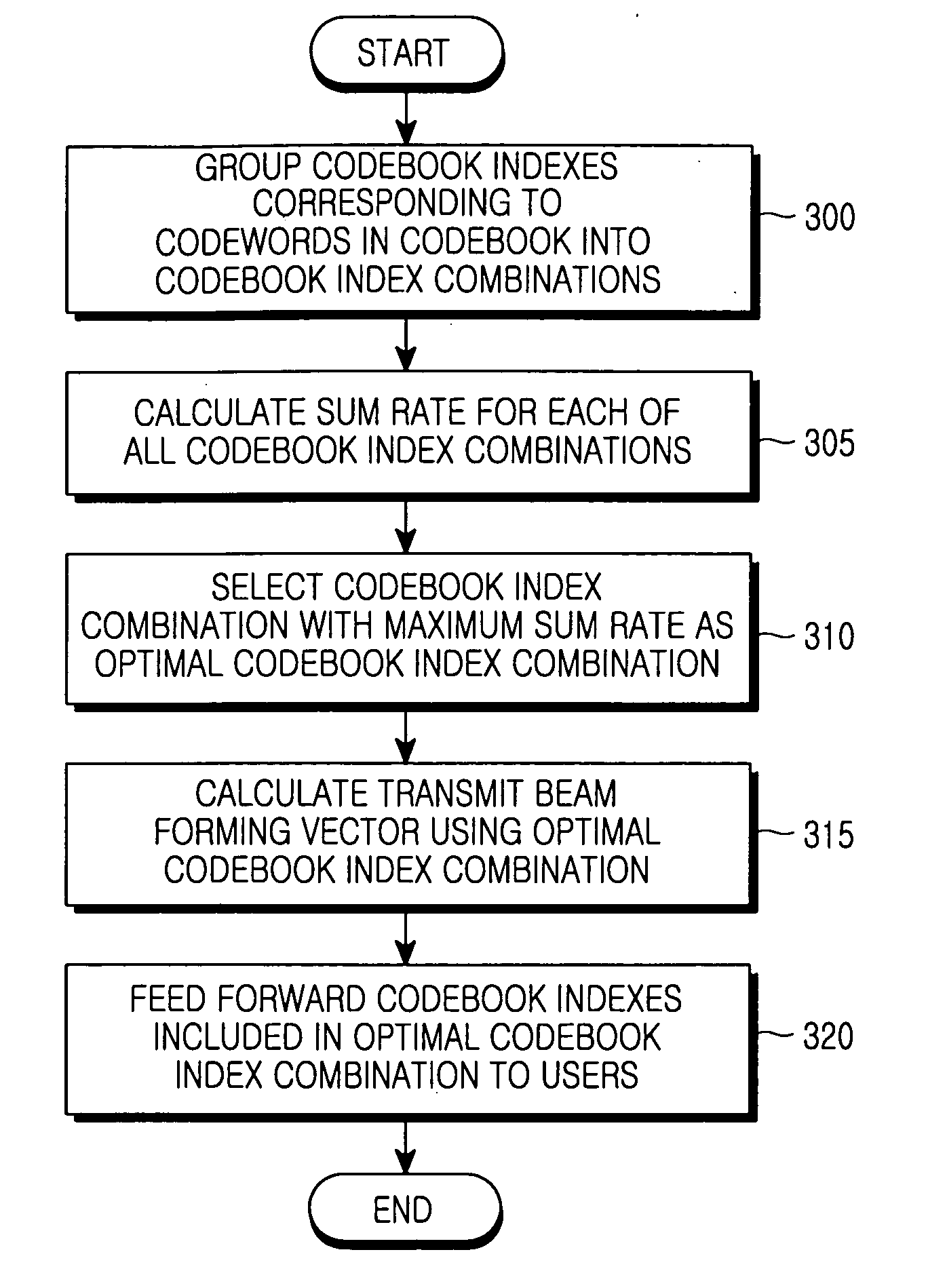
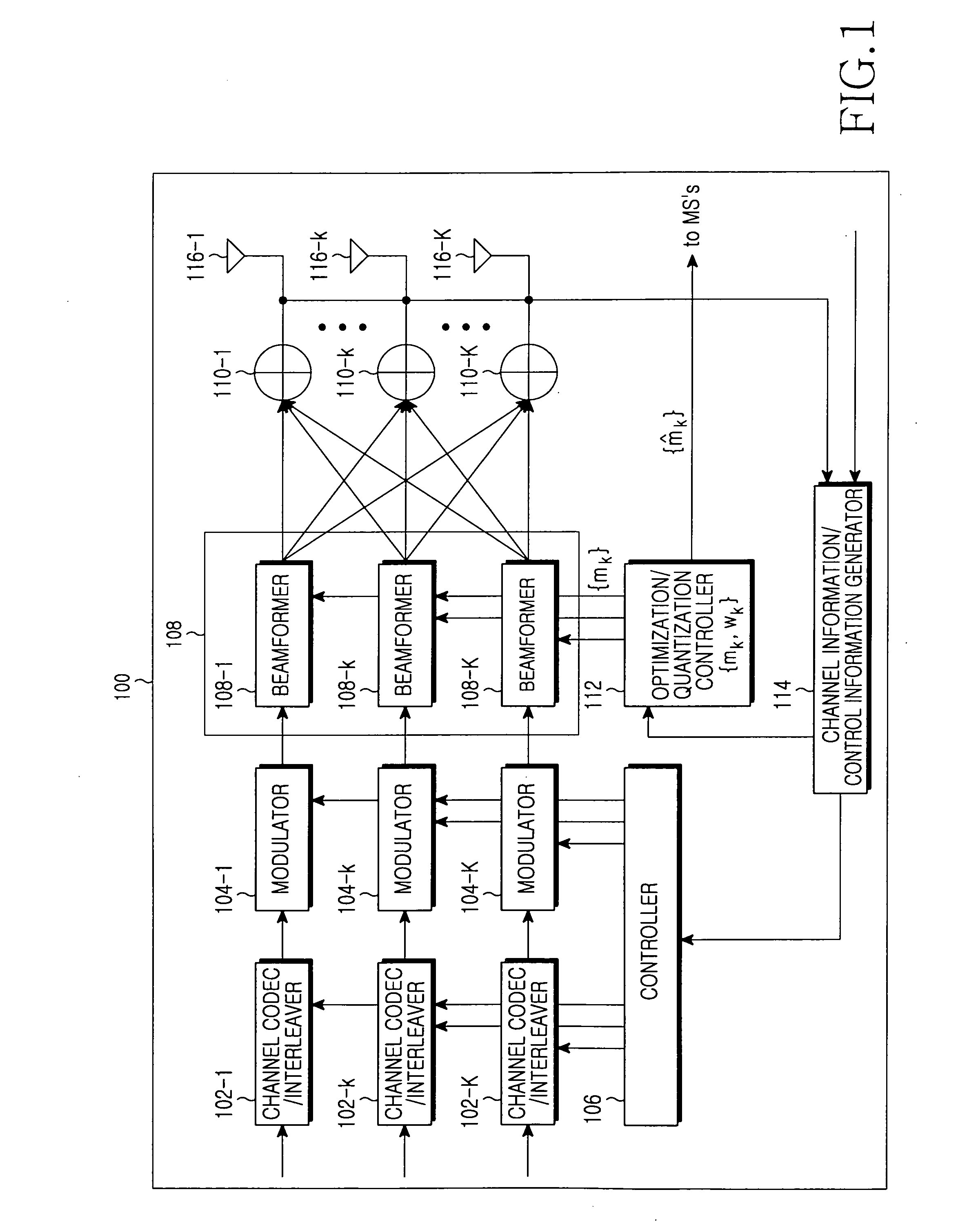
[0014]In accordance with further another aspect of an exemplary embodiment of the present invention, there is provided an apparatus for beamforming in a multi-antenna multi-user communication system. The apparatus includes a controller for grouping codebook indexes included in a codebook into codebook index combinations, calculating a sum of transmission rate for each of the codebook index com

Problems solved by technology

Therefore, signal transmission by the transmission device may be delayed until calculation of transmit / receive beamforming vectors has converged.
On the other hand, when iteration of the iteration algorithm is restricted by compulsion, the transmit / receive beamforming vectors may be calculated incorrectly, causing a reduction in performance.
Therefore, in some cases performance may be degraded due to the quantization.

Method used


Image

  • Apparatus and method for beamforming in a multiantenna multiuser communication system
  • Apparatus and method for beamforming in a multiantenna multiuser communication system
  • Apparatus and method for beamforming in a multiantenna multiuser communication system

Examples


Embodiment Construction

[0021]FIGS. 1 through 3, discussed below, and the various embodiments used to describe the principles of the present disclosure in this patent document are by way of illustration only and should not be construed in any way to limit the scope of the disclosure. Those skilled in the art will understand that the principles of the present disclosure may be implemented in any suitably arranged communication system.

[0022]Embodiments of the present invention will now be described in detail with reference to the figures. In the following description, a detailed description of known functions and configurations incorporated herein has been omitted for clarity and conciseness.

[0023]The present invention provides an apparatus and method for beamforming in a multi-antenna multi-user communication system.

[0024]Before a description of the present invention is given, it is to be noted that a beamforming method proposed by the present invention should satisfy the following assumptions.

[0025]First, ...


PUM


Abstract

A method for beamforming by a transmission device in a multiantenna multiuser communication system. The method includes grouping codebook indexes included in a codebook into codebook index combinations, and calculating a sum of transmission rate for each of the codebook index combinations; selecting a codebook index combination with a maximum sum of transmission rate as an optimal codebook index combination; and transmitting a codebook index corresponding to a particular reception device among codebook indexes included in the optimal codebook index combination, to the particular reception device.

Description

CROSS-REFERENCE TO RELATED APPLICATION(S) AND CLAIM OF PRIORITY[0001]The present application claims the benefit under 35 U.S.C. § 119(a) of a Korean Patent Application filed in the Korean Intellectual Property Office on Mar. 20, 2008 and assigned Serial No. 10-2008-0026081, the disclosures of which are incorporated herein by reference.TECHNICAL FIELD OF THE INVENTION[0002]The present invention relates to an apparatus and method for beamforming in a multi-antenna multiuser communication system.BACKGROUND OF THE INVENTION[0003]Pre-coding and post-processing used by a transmission device of a multi-antenna multi-user communication system are classified into liner types and nonlinear types. The linear pre-coding can be subdivided into unitary pre-coding and non-unitary pre-coding. Coordinated beamforming belongs to non-unitary pre-coding.[0004]In coordinated beamforming, a transmission device calculates pre-coding matrices and receive beamforming vectors (or receive beamforming matrices...

Claims


Application Information

Patent Timeline
IPC IPC(8): H04B7/00
CPCH04B7/043H04B7/0639H04B7/0619H04B7/0452
Inventor KO, EUN-SEOKKWUN, JONG-HYUNGMAZZARESE, DAVIDCHAE, CHAN-BYOUNGHEATH, JR., ROBERT W.
Owner SAMSUNG ELECTRONICS CO LTD
Why Eureka
Try Eureka