
System and method for generating a separated signal

Inactive Publication Date: 2009-10-08
QUALCOMM INC
View PDF83 Cites 28 Cited by
  • Summary
  • Abstract
  • Description
  • Claims
  • Application Information

AI Technical Summary

Benefits of technology

[0007]In some embodiments, the present invention relates to a signal separation method including receiving a set of frequency-domain first signals, wherein each frequency-domain first signals comprises frequency-domain first signal elements corresponding to a plurality of frequencies, and wherein the set of frequency-domain first signals comprises a plurality of signal sources; separating the set of frequency-domain first signals into a set of frequency-domain second signals, wherein the set of frequency-domain second signals comprises a set of separated frequency-domain second signal elements corresponding to individual frequencies of the plurality of frequencies, and wherein each frequency-domain second signal element is assigned an identifier which indicates which of the set of frequency-domain second signals includes the frequency-domain second signal element, and reordering the identifiers corresponding to at least one frequency to improve the coherence of the frequency-domain second signals to produce a set of frequency-domain third signals.
[0010]The one or more constraints may be derived from the set of frequency-domain second signals. Applying one or more constraints to the learning rule may reduce the probability of converging upon a local minimum or maximum. A method disclosed herein may further include receiving a second set of frequency-domain first signals and separating the second set of frequency-domain first signals using the constrained signal separation method. The one or more constraints may include geometric constrains. The geometric constraints may include estimated direction of arrival information and wherein the direction of arrival information is estimated by computing output signal subbands from histograms and / or other statistical techniques using known sensor locations. The one or more constraints may include information regarding spectral or energy characteristics of a signal. The signal may be selected from frequency-domain first signal, a desired output signal, and an undesired output signal. The one or more constraints may include non-derived constraints.

Problems solved by technology

Time-domain methods may achieve better separation performance but may result with more computations than comparable frequency-domain methods.
Also, since in time-domain methods, every filter tap adaptation depends on all other taps, convergence may be slow, prone to local minima and may therefore heavily depend on good initialization.

Method used


Image

  • System and method for generating a separated signal
  • System and method for generating a separated signal
  • System and method for generating a separated signal

Examples


Embodiment Construction

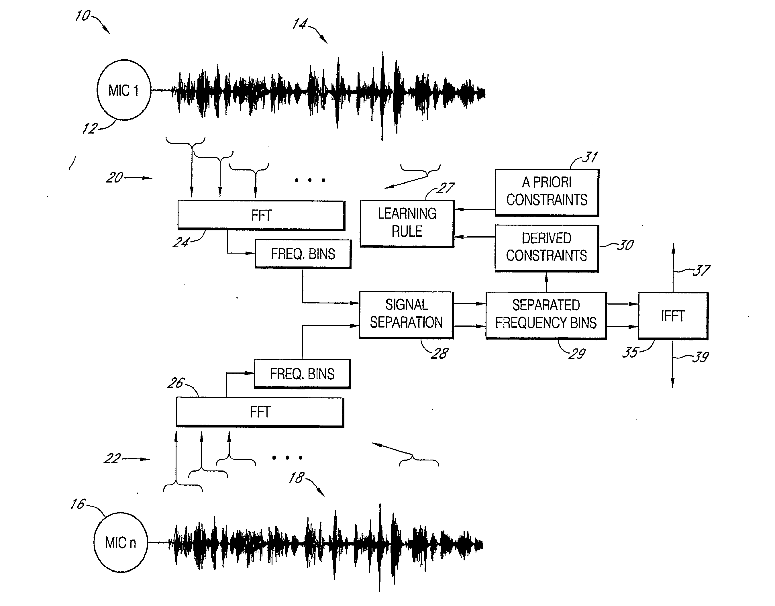
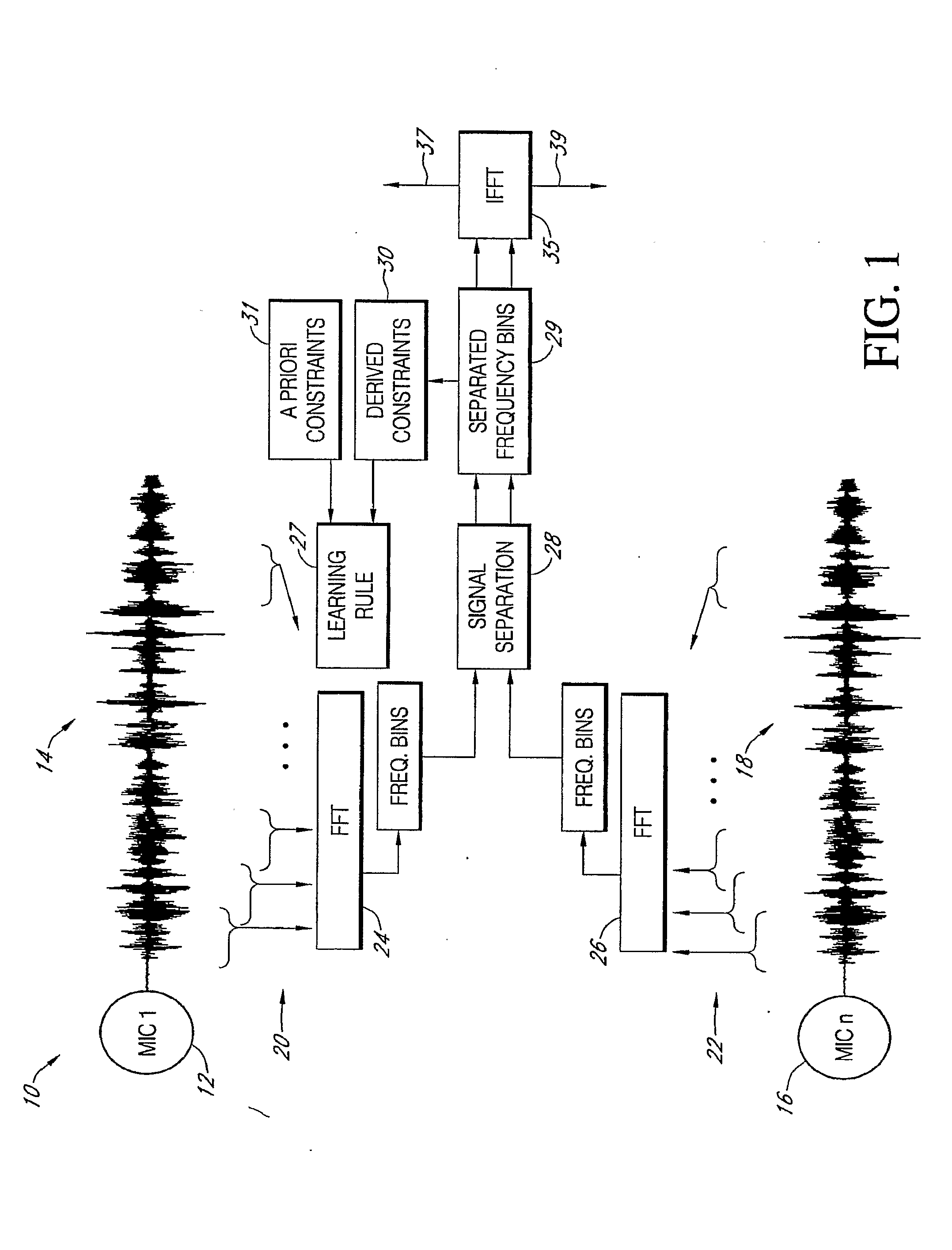
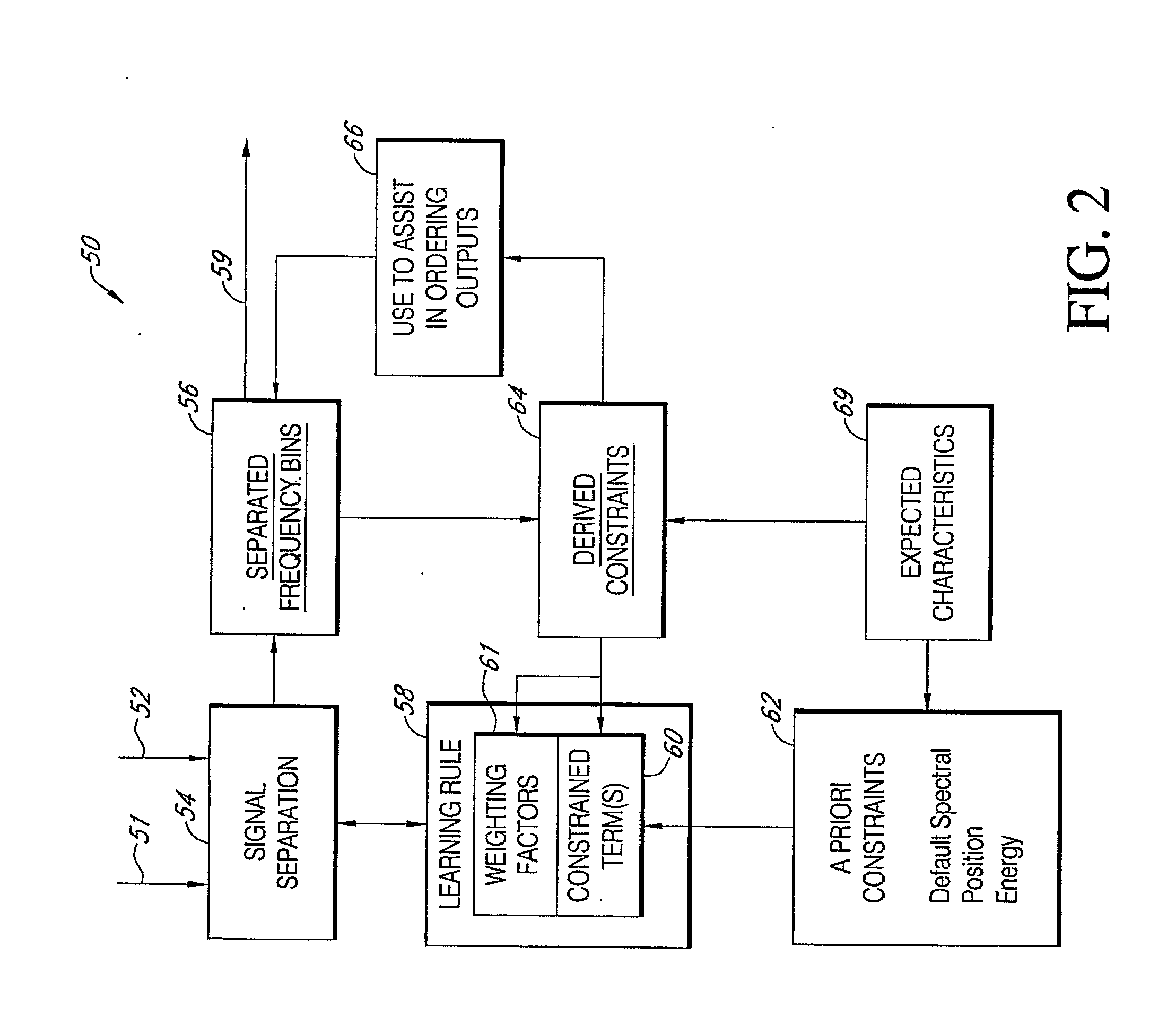
[0037]Independent vector analysis (IVA) has been used in signal separation methods and systems. IVA methods may be implemented in the frequency domain, such that time-domain signal mixtures are first transformed into the frequency domain. Signal separation methods may then be applied to each frequency component of the signal mixtures in order to separate output signal mixtures. Learning rules associated with IVA may maintain that separated output signal elements associated with any given frequency be independent, while correlations may exist across frequencies. IVA methods may therefore comprise fully adaptive filters. However, such methods may be prone to converging upon local minimum and maximum. Further, while the learning rules may provide for subbands within an output signal, they may be insufficient for properly identifying all of the signal elements to the correct source.

[0038]In some embodiments, the present invention relates to improving methods and systems comprising indep...


PUM


Abstract

The present invention relates to blind source separation. More specifically it relates to the blind source separation using frequency domain processes.

Description

CROSS-REFERENCE TO RELATED APPLICATIONS[0001]The present application claims priority from U.S. Provisional Patent Application No. 60 / 777,900, filed on Mar. 1, 2006, and also from U.S. Provisional Patent Application No. 60 / 777,920, filed on Mar. 1, 2006, both of which are incorporated herein by reference in their entireties.BACKGROUND OF THE INVENTION[0002]1. Field of the Invention[0003]The present invention relates to blind source separation. More specifically it relates to blind source separation of signals using frequency domain processes.[0004]2. Description of the Related Art[0005]Acoustic mixtures can be separated using blind source separation (BSS) methods, which may comprise either time- or frequency-domain methods. Time-domain methods may achieve better separation performance but may result with more computations than comparable frequency-domain methods. Also, since in time-domain methods, every filter tap adaptation depends on all other taps, convergence may be slow, prone ...

Claims


Application Information

Patent Timeline
IPC IPC(8): G10L19/14
CPCH04L25/03159G10L21/0272H03H7/30
Inventor CHAN, KWOK-LEUNGVISSER, ERIK
Owner QUALCOMM INC
Features
  • Generate Ideas
  • Intellectual Property
  • Life Sciences
  • Materials
  • Tech Scout
  • Unparalleled Data Quality
  • Higher Quality Content
  • 60% Fewer Hallucinations
Learn More