
Apparatus and method for drying clothes

a clothes dryer and clothes technology, applied in the field of clothes dryers, can solve the problems of heavy power consumption of conventional clothes dryers, significant (many might say excessive) energy consumption, and undesirable effects

Inactive Publication Date: 2009-10-15
BROWN MICHAEL E
View PDF32 Cites 40 Cited by
  • Summary
  • Abstract
  • Description
  • Claims
  • Application Information

AI Technical Summary

Benefits of technology

[0022]It is an object of the present invention to provide an improved device for drying clothing.
[0023]Further objects and advantages of the present invention will become apparent from the following description of the preferred embodiment.

Problems solved by technology

Despite their popularity, conventional clothes dryers have a number of drawbacks.
First among these is that such dryers use significant (many might say excessive) amounts of energy.
This is particularly undesirable in the case of conventional gas-powered and electric clothes dryers, given the costs and environmental impact associated with consuming such energy resources.
Further, not only do conventional clothes dryers demand heavy amounts of power, but also such conventional clothes dryers fail to make efficient use of this power.
In order to heat articles of clothing for drying purposes, these appliances rely on either a gas-based or electric-based heat source that the U.S. government itself (e.g., the Department of Energy) apparently does not consider to be particularly energy efficient.
Indeed, clothes dryers are so inefficient that no clothes dryer on the market is currently listed as qualifying for the U.S. Government's Energy Star rating (see www.energystar.gov).
The poor efficiency of conventional clothes dryers is largely due to the fact that clothes dryers simply do not use large amounts of the energy that is input to the dryers.
Clothes dryers also waste heat energy in other ways.
Further, even to the extent that the heat generated by a clothes dryer reaches and heats the clothes, the energy still is often wasted.
In particular, once the clothes drying cycle has been completed, the heat energy stored in the clothes further is wasted, as the clothes sit idle within the clothes dryer.
Thus, clothes dryers not only require undesirably large amounts of energy in order to operate, but also waste significant portions of that energy.
Although some “condenser dryers” exist in which the air exhausted from the clothes is directed through a condensing coil or heat exchanger to remove moisture from the air and recirculate the air through the dryer, these dryers nevertheless remain inefficient.
The inefficiency of condenser dryers is due to the fact that most of these dryers, like the aforementioned dryers, similarly rely on either gas or electric power in order to heat the air within the clothes dryer.
That is, condenser dryers use the same high energy consuming devices as other conventional dryers.
Additionally, while certain models of condenser dryers do not use any heat sources (but rather dry clothes using room-temperature air), and thus may be more energy efficient than dryers employing heat sources, these dryers are inefficient in their operation since such dryers take much longer periods of time to dry clothes (particularly heavier loads of clothing).
This is an entirely different question than whether the dryer is actually energy efficient, since a dryer that conserves some energy is not guaranteed to be efficient overall.
Nevertheless, such solar dryers are still not considered to be energy efficient, because they are forced to rely heavily upon one or more “back-up” heat sources, typically electric resistance heat elements.
Such back-up heat sources are necessary insofar as the units are not always able to generate adequate heat from the sun's rays, for example, during evenings / nightfall, heavy overnight snowfall, mostly cloudy days, winter months, or during the presence of other weather related inhibitors.
That is, during times when insufficient solar energy is received by the units, they revert back to conventional dryers.
A further disadvantage of solar-based dryers has to do with their physical layout.
Early models of solar-based dryers lacked the ability to store solar-heated water inside insulated storage tanks.
Nevertheless, tank placement, along with building and installation cost, still are not favorable to the public.
Additionally, while conventional clothes dryers are generally safe machines, such clothes dryers remain a potential source of damage and injury, particularly to the extent that occasionally clothes dryers can start on fire.
Among the primary reasons that conventional dryers catch fire is that dried-out lint / dust accumulates within the dryer and eventually makes its way back to the heating element, where it can potentially ignite.
Further, while conventional clothes dryers do successfully dry clothes, the dry, heated air that is blown onto the clothes within the clothes dryers does not always produce dry clothes having desirable characteristics.
In particular, when dryers are operated somewhat too long, the clothes being dried can become excessively dry and even burnt or scorched.
Not only does this excessive drying and resultant scorching potentially damage the clothes, but also as a result the clothes coming out of the dryer tend to have a somewhat unpleasant, burnt smell.
While certain products such as fabric softeners (e.g., sheets that can be added into the dryer along with the clothes) are available for enhancing the softness and smell of the clothes being dried (in addition to reducing static electricity in those clothes), such fabric softeners do not fully resolve the problems that result from excessive drying.

Method used


Image

  • Apparatus and method for drying clothes
  • Apparatus and method for drying clothes
  • Apparatus and method for drying clothes

Examples


Embodiment Construction

[0043]For the purposes of promoting an understanding of the principles of the invention, reference will now be made to the embodiment illustrated in the drawings and specific language will be used to describe the same. It will nevertheless be understood that no limitation of the scope of the invention is thereby intended, and alterations and modifications in the illustrated device, and further applications of the principles of the invention as illustrated therein are herein contemplated as would normally occur to one skilled in the art to which the invention relates.

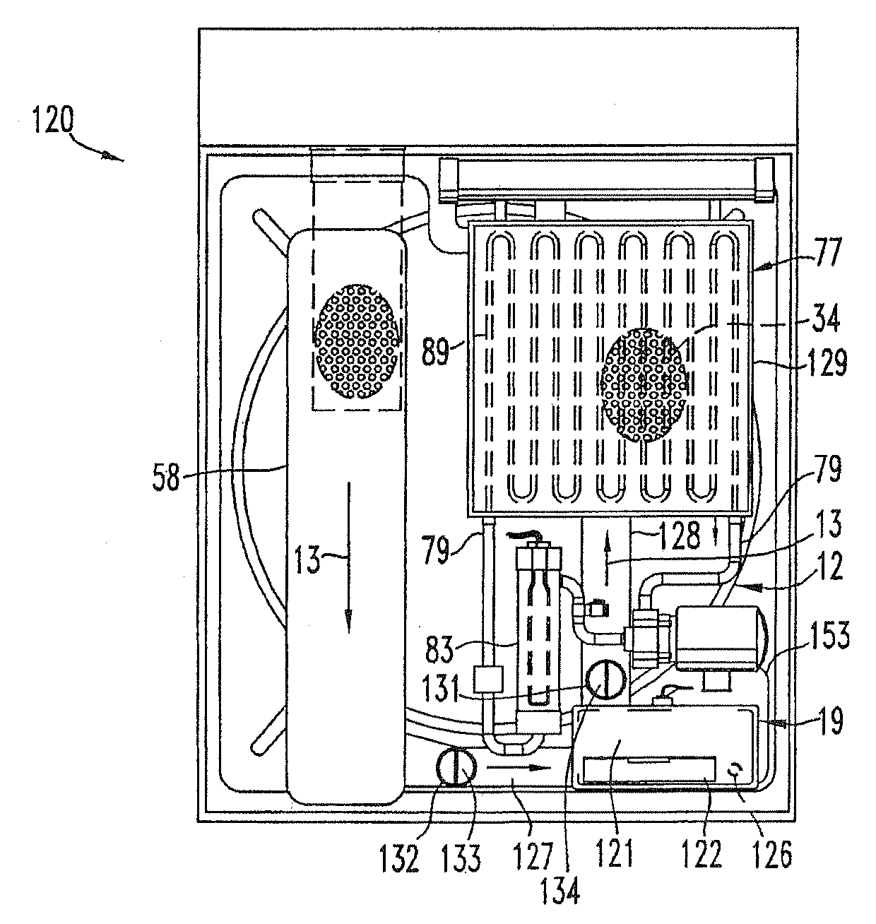
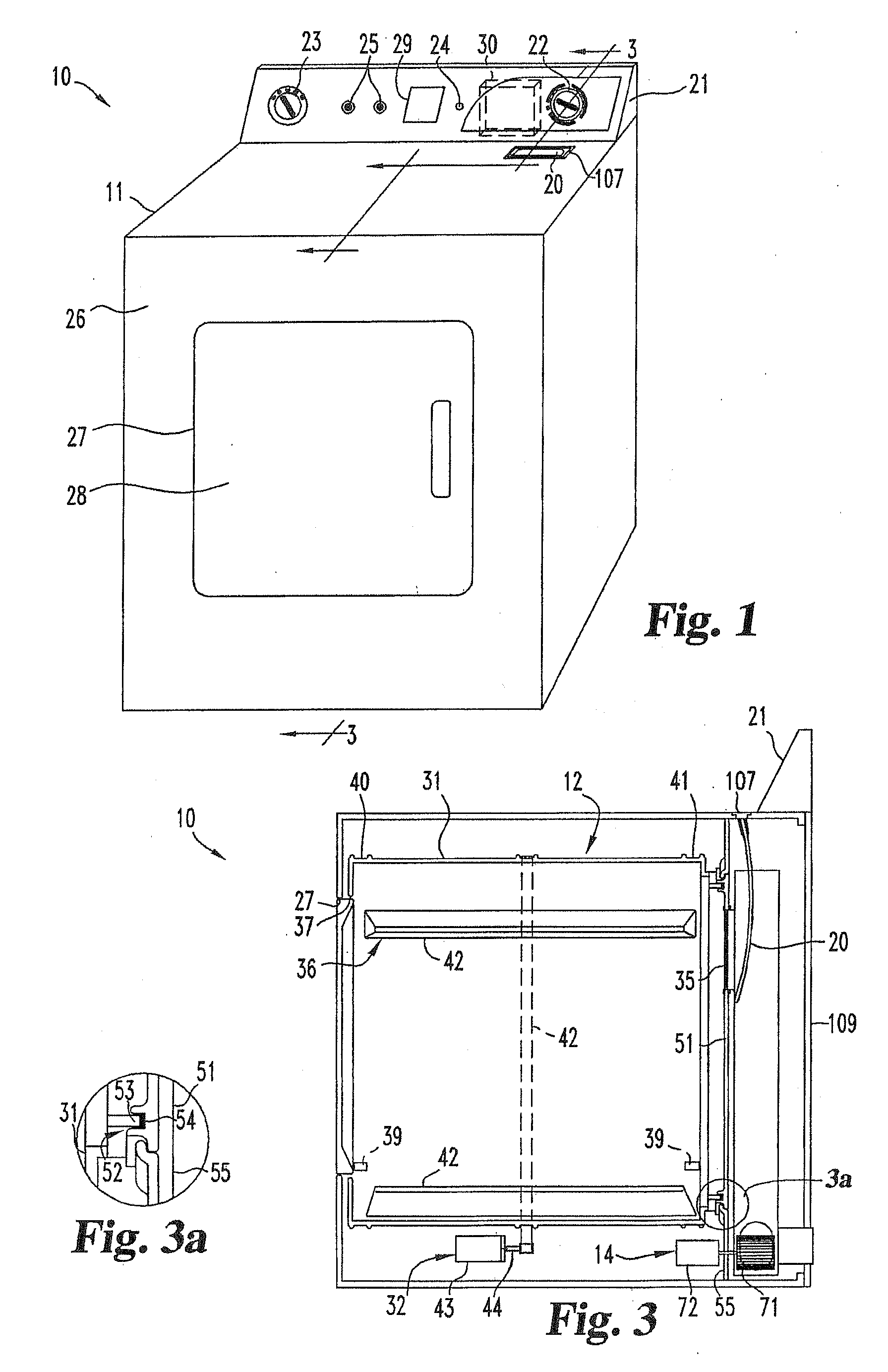
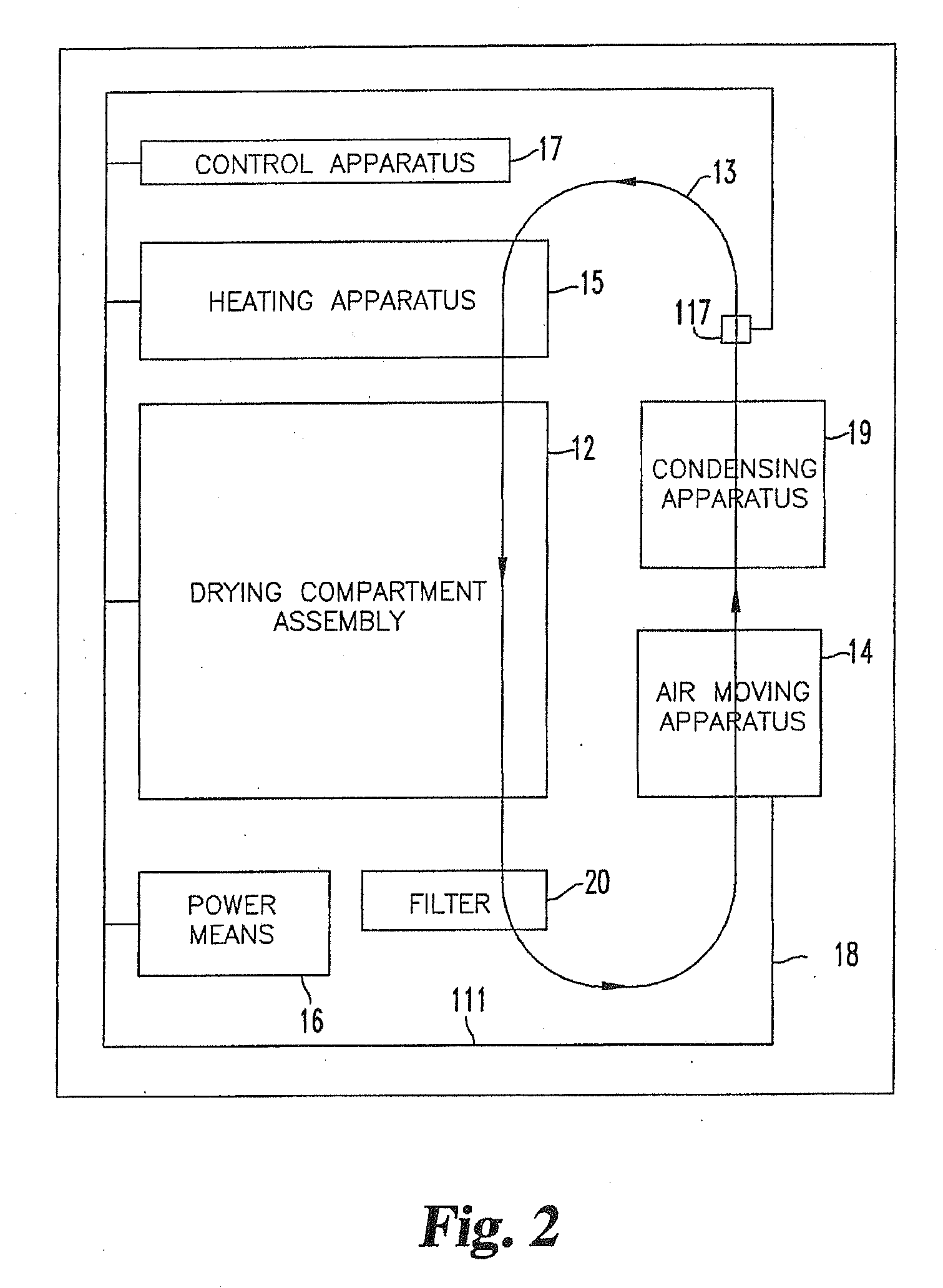
[0044]Referring to FIGS. 1-3, there is shown an apparatus for drying clothes, also referred to herein as a drying machine and a clothes dryer 10, in accordance with one embodiment of the present invention. The present embodiment is directed to drying articles of clothing, however it should be understood that use of the word clothing in this regard is intended to cover any and all items that would be appropriate to put in...


PUM


Abstract

A drying apparatus and method are disclosed. The drying apparatus includes a drying compartment and a heating device that heats air to be provided to the compartment. The heating device includes a coil through which is conducted a heated liquid, and the air is heated as it passes along the coil. The heated liquid can be provided from a source internal or external to the drying apparatus and in at least some embodiments is heated water provided from a hydronic heating device located internal to the drying apparatus. In at least some embodiments, the heated air provided through the drying compartment is returned to the heating device and recirculated through the compartment. In at least some of these embodiments, the heated air emanating from the drying compartment passes through a condensing device that removes moisture from the air before it is returned to the heating device.

Description

CROSS REFERENCE TO RELATED APPLICATIONS[0001]The present application claims the benefit of U.S. Provisional Patent Application Ser. No. 60 / 648,904, filed Feb. 1, 2005 entitled “Hydronic Clothes Dryer”, which is hereby incorporated by reference in its entirety, and is a continuation of U.S. patent application Ser. No. 11 / 275,877, filed Feb. 1, 2006 entitled “Apparatus and Method for Drying Clothes,” which is hereby incorporated by reference in its entirety.FIELD OF THE INVENTION[0002]The present invention relates to drying machines, and in particular, to clothes dryers such as those used in homes, laundromats and other facilities.BACKGROUND OF THE INVENTION[0003]Clothes dryers are one of the most ubiquitous labor-saving appliances, and are used in a variety of facilities ranging from personal homes and apartment complexes to laundromats and many other commercial facilities such as hotels and hospitals. Clothes dryers, which typically are either electric or gas-powered devices (althou...

Claims


Application Information

Patent Timeline
Patent Type & Authority Applications(United States)
IPC IPC(8): F26B21/00F26B25/06H05B3/78F24J2/04F28F3/00G05D23/00
CPCD06F58/20Y02B40/74Y02B10/20D06F58/263Y02B40/18
Inventor BROWN, MICHAEL E.
Owner BROWN MICHAEL E
Learn More