Rotor and device for the comminution of input material

a rotor and input material technology, applied in the field of rotors for the comminution of input materials, can solve the problems of inability to achieve the effect of increasing increasing the rotor length without achieving an increase in reducing the effective working area of grinding, etc., to achieve the effect of improving the rotor and the device, compact design, and precise grinding

Active Publication Date: 2009-09-10
PALLMANN MASCHFAB GMBH & CO KG
View PDF14 Cites 7 Cited by
  • Summary
  • Abstract
  • Description
  • Claims
  • Application Information

AI Technical Summary

Benefits of technology

[0016]It is therefore an object of the present invention to improve rotors and devices with regard to the above-described disadvantages; in particular, a rotor in accordance with the invention should permit a compact design, precise grinding and safe, economical operation.

Problems solved by technology

These design types of rotors always prove disadvantageous if an axially compressed design is important because of space conditions.
The attachment of the supporting discs to the face of the rotor increases the rotor length without achieving an increase in the effective working area for grinding.
In addition, such a design is relatively expensive to manufacture and assemble and in the case of manufacturing and assembly inaccuracies, rapidly leads to imbalance of the rotor and losses of round.
Furthermore in the case of overload on the rotor, for example if it is blocked because of unintended foreign body input, considerable damage to the grinding unit takes place, since absolute force locking is produced between the drive side and rotor.
These two solutions also result in absolute force locking between the drive shaft and the rotor disc, so that in the case of overload on the device, damage to the grinding unit is to be feared.
Furthermore, the formation of accurately fitting grooves on the shaft and rotor discs implies a considerable increase in costs for manufacturing and assembly.
Although the welding together of the rotor discs results in reliable power transmission of the driving torque into all rotor discs, it has the drawback that all rotor discs form a rigid, non-removable rotor unit which is difficult to handle in the case of disassembly or repairs.

Method used


Image

  • Rotor and device for the comminution of input material
  • Rotor and device for the comminution of input material
  • Rotor and device for the comminution of input material

Examples


Embodiment Construction

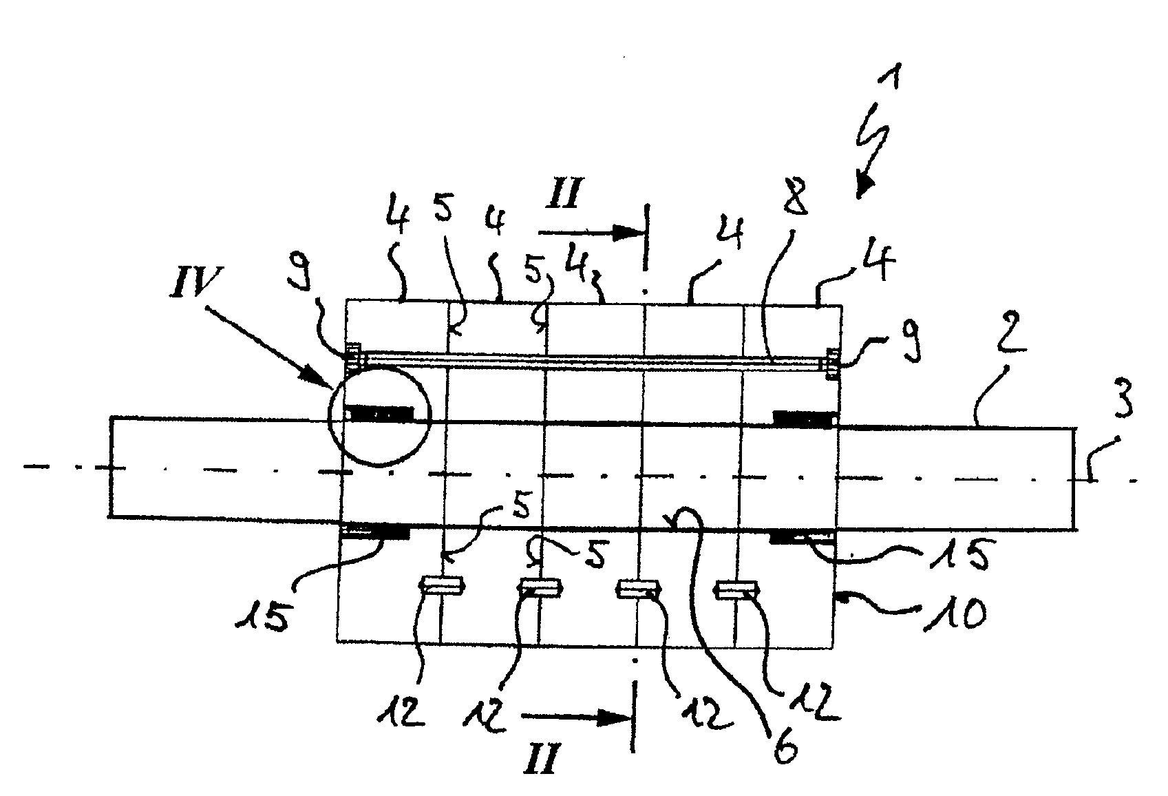
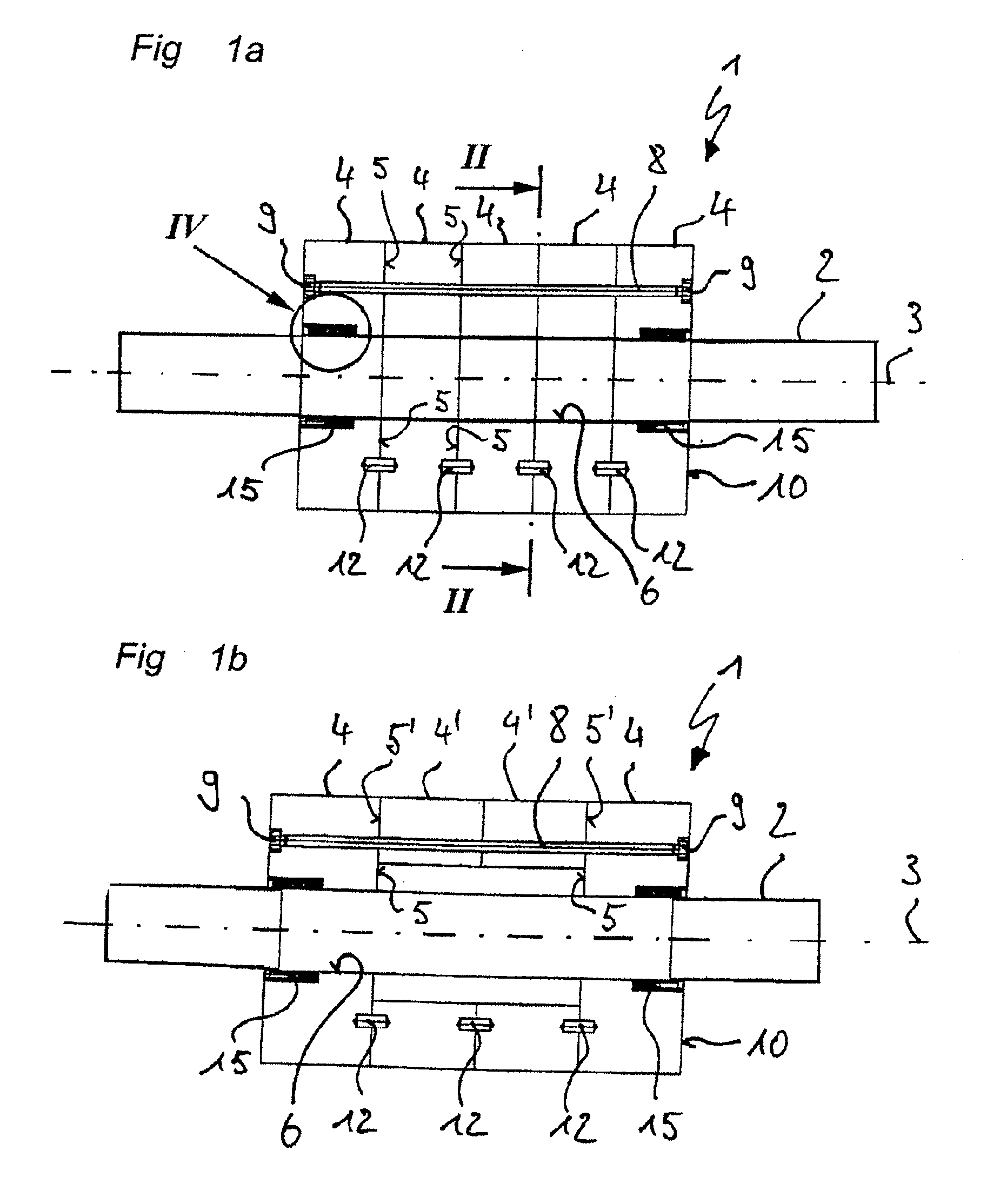
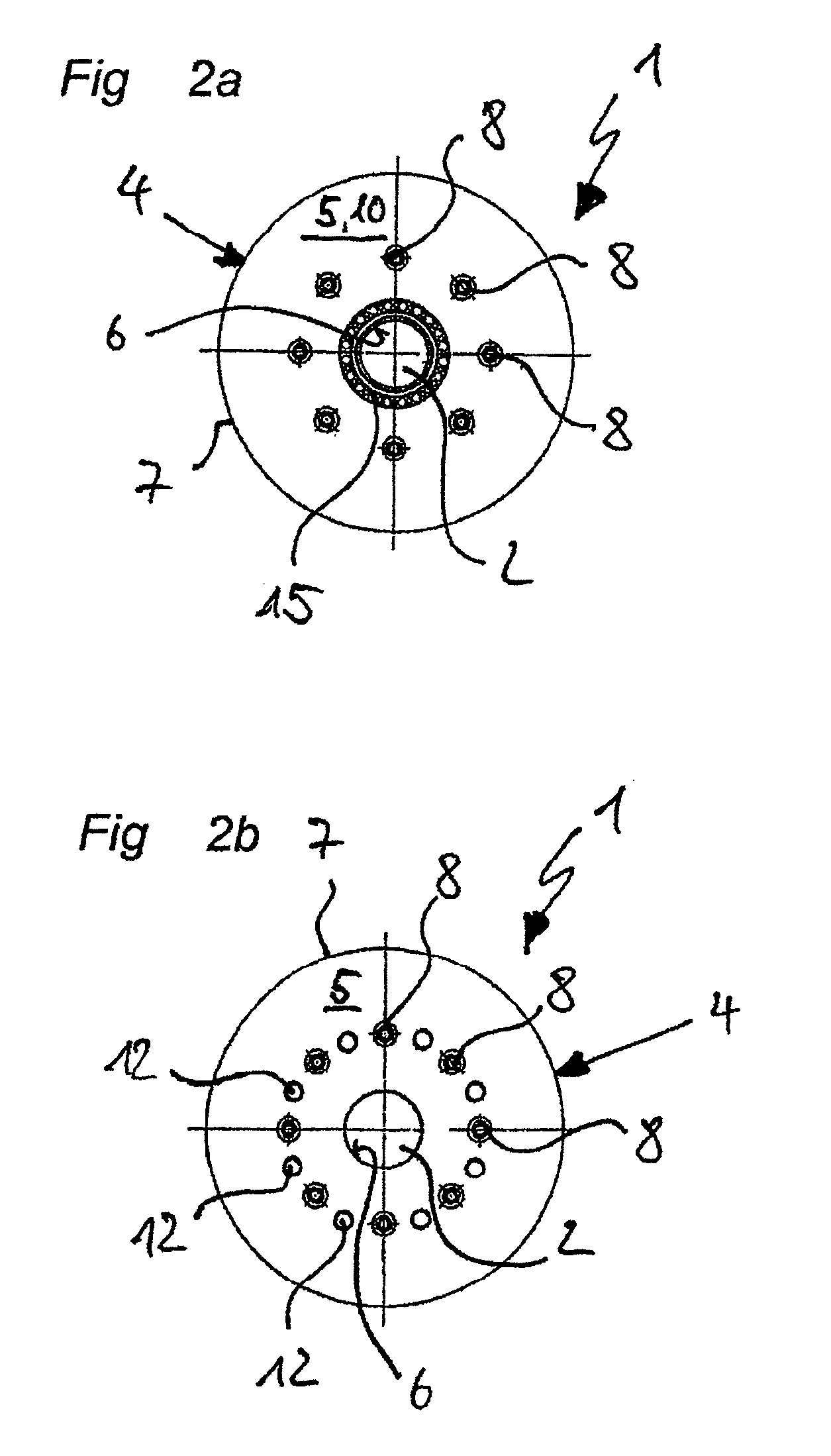
[0036]FIGS. 1a, 2a and 2b show a first embodiment of a rotor 1 in accordance with the invention, which for example is suitable for accomplishing the size reduction of input materials of a wide range of types within a shredder or a cutting mill. A device suitable for the use of rotor 1 is, for example, described in DE 102006056542 A1, which corresponds to U.S. Publication No. 20080135658, the entire content of which is incorporated herein by reference.

[0037]The rotor 1 shown in FIG. 1a has a continuous drive shaft 2 with a longitudinal axis 3, the free ends of which are intended to be retained rotatably in axial bearings of the device, not shown. In the operation of the device in accordance with the invention, the drive shaft 2 is impinged with a driving torque to generate a rotational motion. In the center region on the drive shaft 2, in a coaxial arrangement, five successive rotor discs 4 are placed, the front faces 5 of which are in contact with one another.

[0038]As is apparent fr...


PUM


Abstract

A rotor and device for the comminution of input material is provided. The rotor includes a drive shaft on which a predetermined number of rotor discs are provided and over the circumference of which grinding tools are arranged. In accordance with an embodiment, it is provided that frictional connection elements are arranged between the rotor discs forming axial ends of the rotor and the shaft for transferring a torque, and that power transmission elements are arranged in a contact surface of two adjacent rotor discs and that the rotor discs can be clamped together with axially acting clamping elements.

Description

[0001]This nonprovisional application claims priority under 35 U.S.C. §119(a) to German Patent Application No. 10 2008 013 232, which was filed in Germany on Mar. 7, 2008, and which is herein incorporated by reference.BACKGROUND OF THE INVENTION[0002]1. Field of the Invention[0003]The present invention relates to a rotor for the comminution of input materials and a device with such a rotor.[0004]2. Description of the Background Art[0005]In the comminution of materials, devices with a grinding unit comprising a rotor have proven to be useful. The rotor is essentially made up of a shaft and rotor discs arranged on it, with the grinding tools distributed over the circumference of the discs. The grinding tools can be made from knives, rigid or swinging suspended hammers, cutting tools or the like. As a rule, the rotor has assigned to it a stator, which is equipped with counter-knives, impact surfaces or screening surfaces, or an additional rotor, the rotor discs of which interact with t...

Claims


Application Information

Patent Timeline
Patent Type & Authority Applications(United States)
IPC IPC(8): B02C13/30
CPCB02C18/146B02C13/04
Inventor PALLMANN, HARTMUT
Owner PALLMANN MASCHFAB GMBH & CO KG
Why Eureka
Try Eureka