Insufflation tube comprising a humidifying material and a heating element, for laparoscopy

a technology of insufflation tube and heating element, which is applied in the field of laparoscopy tubes with integrated heating elements, which can solve the problems of inability to keep the humidification rate of gas for different flow rates at uniform levels, considerable disadvantages, and devices known from the prior ar

Active Publication Date: 2015-07-16
W O M WORLD OF MEDICINE GMBH
View PDF5 Cites 7 Cited by
  • Summary
  • Abstract
  • Description
  • Claims
  • Application Information

AI Technical Summary

Benefits of technology

[0011]It is therefore the object of the present invention to provide an improved device for heating and humidifying insufflation gases, which does not exhibit the mentioned drawbacks.

Problems solved by technology

The devices known from the prior art have technical drawbacks.
Due to the size and the weight of the chamber, it may be disturbing in the near operational field to the doctor in charge.
Further, the humidification rates of the gas for different flow rates cannot be kept at uniformly high levels.
This has considerable disadvantages when maintaining the pneumoperitoneum.
In particular, if high refill rates are required (for instance when using suction pumps), the insufflation capacity may under certain conditions not be sufficient, and the pressure in the abdominal cavity may possibly not be maintained.
Further, the introduction of the additional chamber for the humidification of the gas is disadvantageous for the production cost of the insufflation tube.
The additionally required parts will substantially increase the cost.

Method used


Image

  • Insufflation tube comprising a humidifying material and a heating element, for laparoscopy
  • Insufflation tube comprising a humidifying material and a heating element, for laparoscopy
  • Insufflation tube comprising a humidifying material and a heating element, for laparoscopy

Examples


example 1

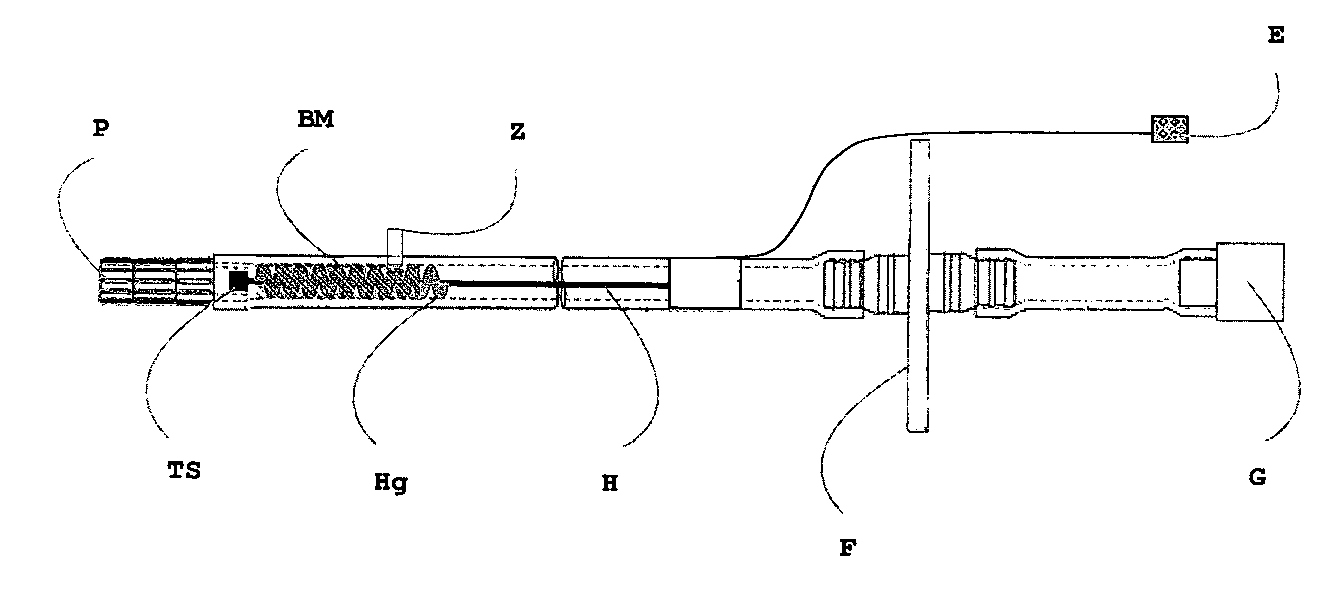
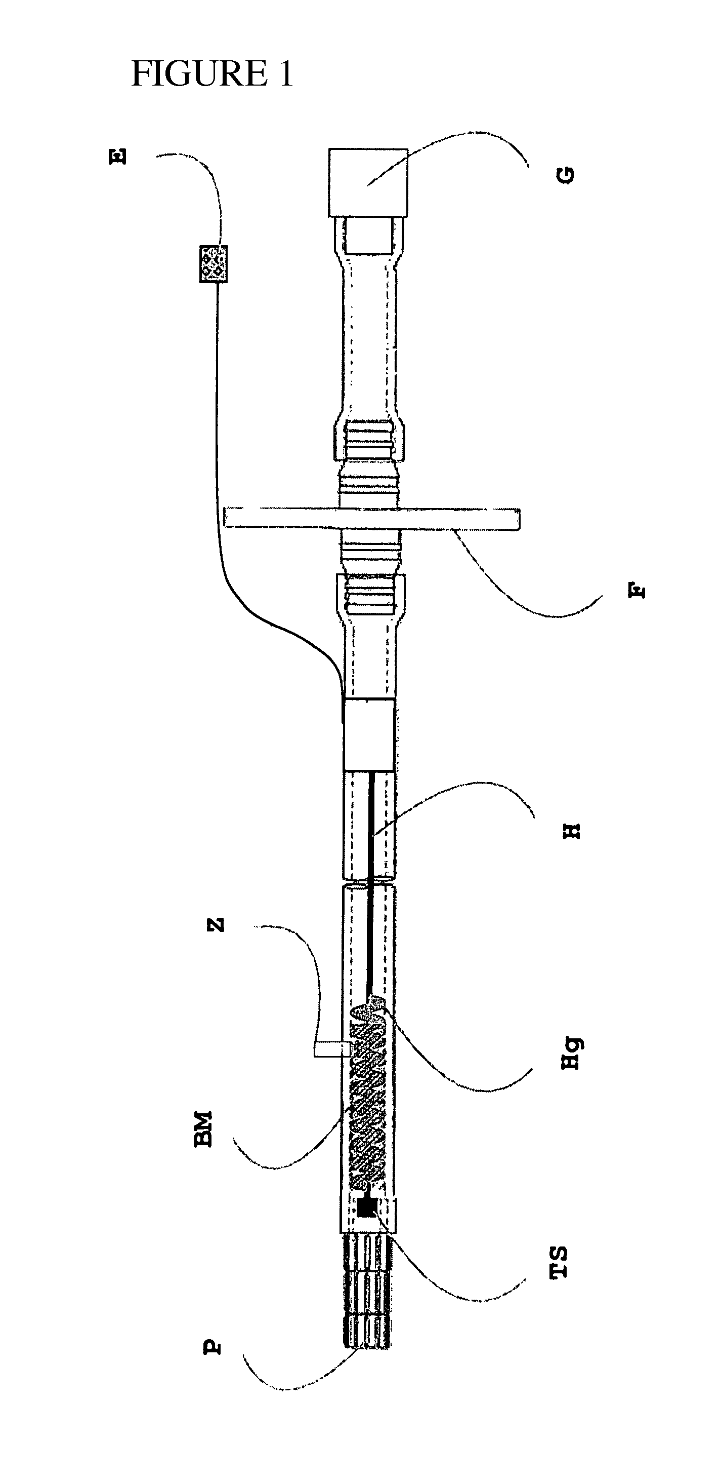
[0038]In a tube of PVC, which has a length of 3 m, a helical heating element is positioned over a distance of 90 cm. The heating element consists of nickel-chrome. The heating element is supplied with power via electrical leads to electrical connection E. By means of a voltage of 24 V, an electrical heating power of ˜30 watts is achieved.

[0039]A sterile gauze bandage as a humidifying material BM is wound around the heating element Hg, so that the heating element has essentially everywhere immediate contact with the humidifying material. It is the following material: cotton 68%, polyamide 24%, elastane 8%. In addition, a temperature probe TS is provided at the exit of the tube (see FIG. 1).

[0040]Before starting the laparoscopy, the porous material is humidified with ˜10 ml sterile water. Feeding the water is achieved via the additional access / via the patient-side end of the tube. The tube is provided at its patient-side end P with a Veress needle that is introduced into the abdomen o...

example 2

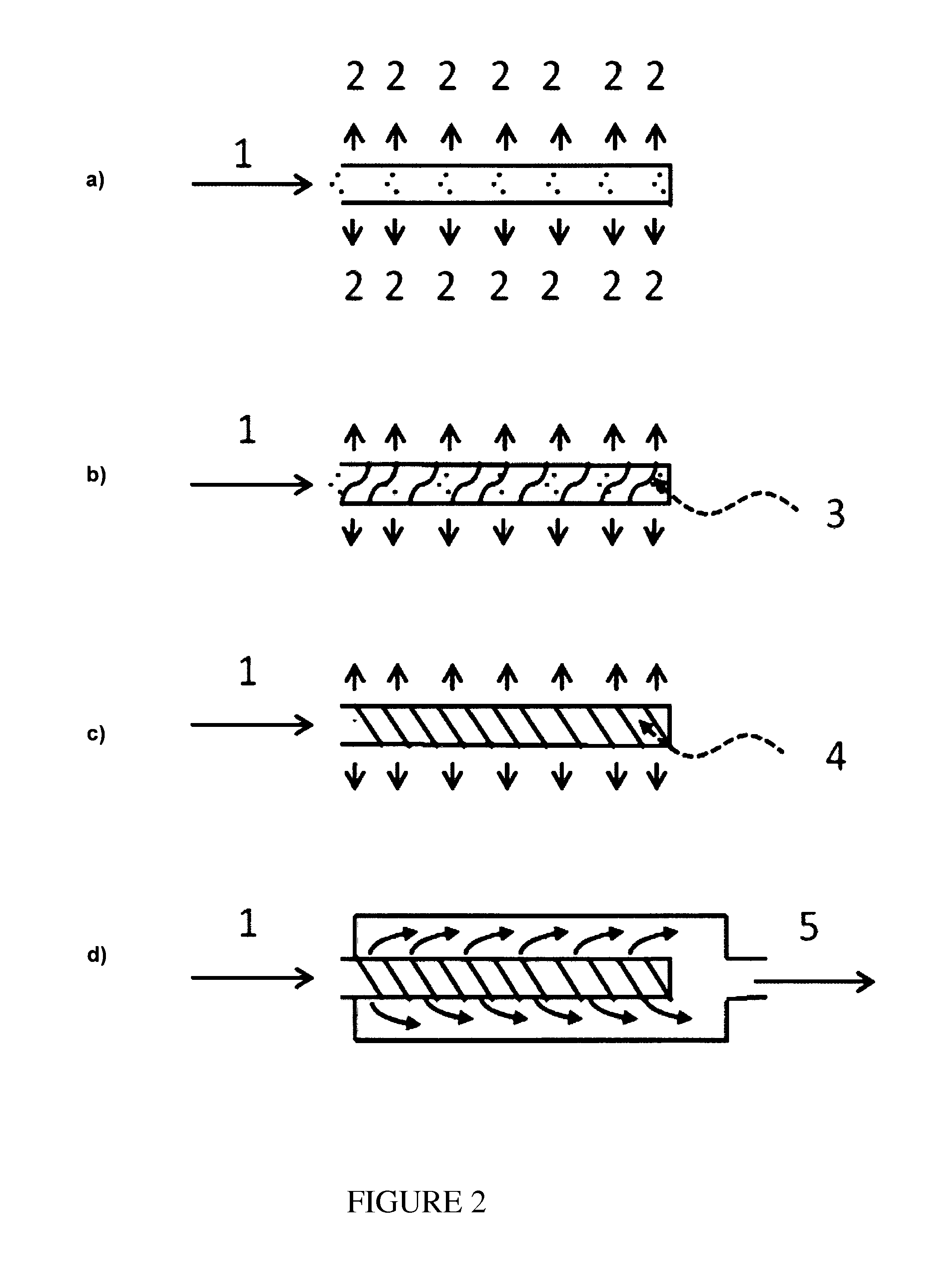
[0042]A nickel-chrome wire is wrapped around a braided tube with a length of 50 cm made of the material PET (diameter 3 mm) that has a multiplicity of openings (<0.5 mm) over the complete length. Over the nickel-chrome wire, a layer of a sterile cotton fabric is applied. The covered tube formed in this way is introduced into a PVC tube of 3 m length (diameter 10 mm) The heating element is supplied with power via electrical leads. By means of a voltage of 24 volts, an electrical heating power of approx. 50 watts is achieved. The above humidifying material further contains, in addition to cotton, polyamide and elastane (see Example 1). Furthermore, a temperature probe is provided at the exit of the tube.

[0043]The gas supply takes exclusively place via the inner tube.

[0044]Such an insufflation tube according to Example 2 is shown in FIG. 2. FIG. 2a shows such a tube that has a multiplicity of openings on the outer surface. The gas supply (1) is shown on the left-hand side of the figure...


PUM


Abstract

The present invention relates to a tube with an integrated heating element for laparoscopy. By means of a humidifying material in the interior of the tube, the gas introduced during laparoscopy is heated and humidified.

Description

BACKGROUND OF THE INVENTION[0001]The present invention relates to a tube with an integrated heating element for laparoscopy. By means of a humidifying material in the interior of the tube the gas introduced during laparoscopy is heated and humidified. The present patent application claims the priorities of the previous German applications DE 102013000492.6 (date of filing: 15 Jan. 2013) and DE 1020130100967.6 (date of filing: 18 Jun. 2013).[0002]Laparoscopy is a medical intervention by means of which the abdominal cavity and the organs therein can be visually examined For this purpose, small skin incisions (0.3-2 cm) in the abdominal wall are typically made, and a trocar is introduced therethrough, which in turn can accommodate an optical device. With the aid of a special endoscope (laparoscope), the abdomen can be examined. In diagnostic laparoscopy, the abdomen is only visually inspected, and in a therapeutic process, operative interventions can also be performed.[0003]Typically, ...

Claims


Application Information

Patent Timeline
Patent Type & Authority Applications(United States)
IPC IPC(8): A61B17/34A61M16/16A61B1/313A61M13/00
CPCA61B17/3474A61M13/003A61M2205/3653A61B1/3132A61M2205/3372A61M16/16A61M2202/0225A61M2205/3368A61M2210/1021A61M16/18
Inventor KOETH, YVES
Owner W O M WORLD OF MEDICINE GMBH
Why Eureka
Try Eureka