Heat Pump System

a heat pump and heat exchange technology, applied in solar heat collectors, solar thermal energy generation, solar heat collectors for particular environments, etc., can solve the problem that the effect of a heat pump is not normally sufficient to cope with heating unassisted, and achieve the effect of increasing or reducing ventilation/air replacement, reducing the inward flow of outdoor air, and increasing or reducing the efficiency of the heat pump

Active Publication Date: 2009-10-15
KODEDA CLEANTEC
View PDF12 Cites 9 Cited by
  • Summary
  • Abstract
  • Description
  • Claims
  • Application Information

AI Technical Summary

Benefits of technology

[0007]The invention proposes a heat pump system comprising a heat pump so arranged as to permit the taking up of thermal energy from outdoor air and the giving off of thermal energy to a different medium, together with an external space adapted to permit heating of the outdoor air with the help of solar radiation, the system being so arranged as to conduct the outdoor air to the heat pump via the external space. The invention is characterized in that the heat pump system comprises means for regulating the flow of the outdoor air to the external space. In other words, the system comprises means for increasing or reducing the ventilation / air replacement in the external space, should the need arise. An advantageous effect of this construction is that, by regulating the inward flow of outdoor air, it is possible to regulate the temperature inside the external space, which can be utilized in turn to increase the efficiency of the heat pump. In a first example, the inward flow of outdoor air can be minimized, that is to say the air can be caused to recirculate inside the external space for as long as the temperature in the external space, thanks to irradiated solar energy, remains higher than in the surrounding outdoor air. In most situations, this has a positive influence on the efficiency of the heat pump. In a second example, the inward flow of outdoor air can be maximized when the temperature inside the external space is lower, or is in the process of becoming lower, than the temperature of the ambient air, which can occur when the quantity of irradiated heat is less than the thermal take-off by the heat pump. Thanks to the solution in accordance with the invention, the temperature inside the external space can be prevented from falling below the temperature of the outdoor air. In this way, a situation is avoided in which the efficiency of the heat pump is reduced by the fact that it is obliged to operate with cooled outdoor air, which can occur, for example, with a construction in accordance with U.S. Pat. No. 4,378,787, in which no means are available for controlling the replacement of air in the external space. The thermal energy that is transferred to the second medium in accordance with the invention may be utilized, for example, for heating a domestic hot water system in a neighbouring building or for heating an installation such as a swimming pool.
[0008]In a first preferred embodiment of the invention, the heat pump system comprises a first fan so arranged as to generate an inward flow of outdoor air into the external space. This provides the possibility of simple and effective control of the inward flow. The fan is preferably so arranged as to generate an outward flow of air from the external space and, in addition, the system preferably comprises an inlet which permits the inward flow of outdoor air into the external space. In this way, the fan indirectly generates an inward flow of outdoor air into the external space, at the same time as it is provided with increased possibilities to determine how much air will exit from the external space. The fan can very well constitute an integral part of the heat pump, which permits the use of many conventional outdoor air heat pumps.
[0011]In a fourth preferred embodiment of the invention, the heat pump system comprises an adjustable sun screening device so adapted as to be capable of screening the solar radiation and, by so doing, of limiting the heating of the outdoor air inside the external space. In this way, additional possibilities are provided for regulating the temperature inside the external space.

Problems solved by technology

In colder climates, the effect of a heat pump is not normally sufficient to cope with heating unassisted, for which reason buildings are equipped with supplementary heating systems.

Method used


Image

  • Heat Pump System
  • Heat Pump System

Examples


Embodiment Construction

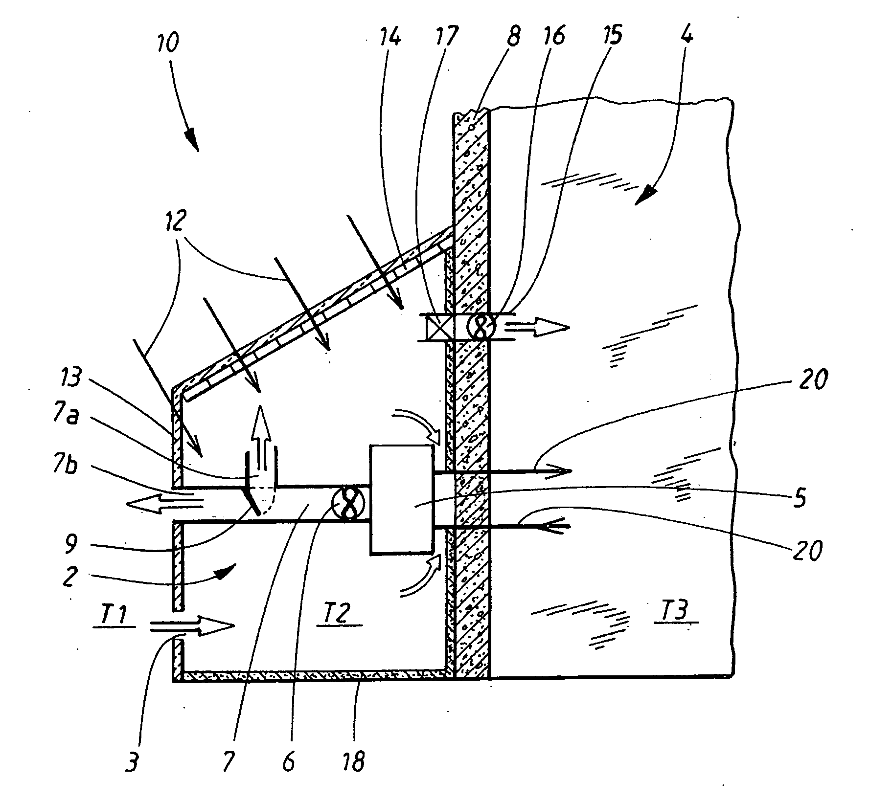
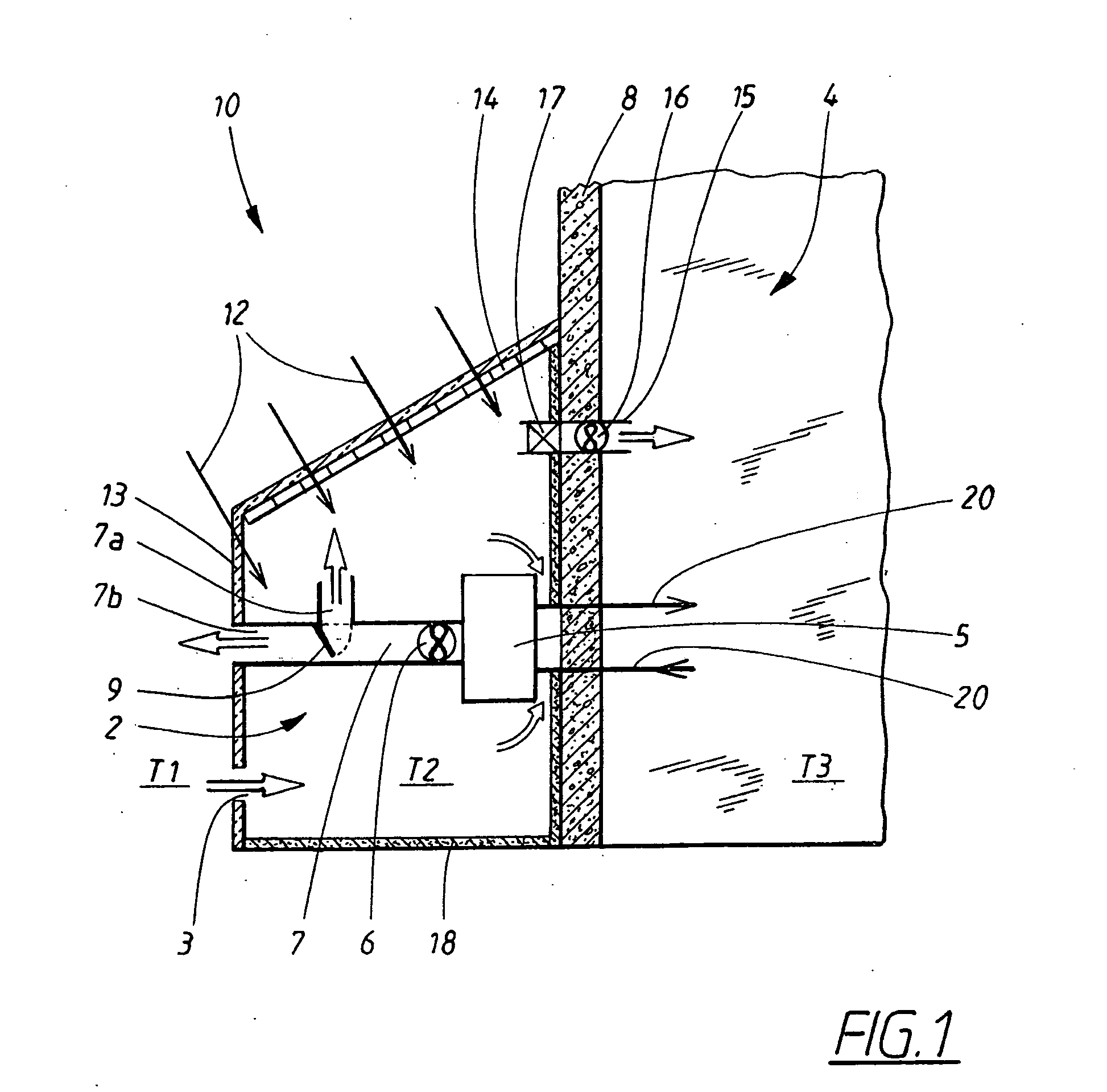
[0014]Depicted schematically in FIG. 1 is a preferred embodiment of a heat pump system 10 according to the invention. A heat pump 5 is so arranged as to take up thermal energy from outdoor air from an external space 2 adapted to permit heating of the outdoor air by the use of solar radiation 12, and to give off thermal energy to a building 4 by heating water. The external space 2 can be in the form of a greenhouse, a glass cupola, a glazed courtyard or some other glazed construction on or in connection to the wall 8 or roof of the building 4. In the conventional way, the heat pump 5 comprises a number of components in the form of an evaporator, a compressor, a condenser, an expansion valve and a cooling medium duct for circulating a cooling medium (which components are not depicted in the figure). The heat pump 5 in turn is arranged in or in conjunction with both the external space 2 and the building 4 in such a way that the air inside the external space 2 comes into contact with th...


PUM


Abstract

The invention relates to a heat pump system (10) comprising a heat pump (5) so arranged as to permit the taking up of thermal energy from outdoor air and the giving off of thermal energy to another medium (20), and an external space (2) adapted to permit heating of the outdoor air by the use of solar radiation (12), the system (10) being so arranged as to conduct the outdoor air to the heat pump (5) via the external space (2). The invention is characterized in that the heat pump system (10) comprises means (3, 6, 7, 7a, 7b, 9) for regulating the flow of the outdoor air to the external space (2).

Description

TECHNICAL FIELD[0001]The invention relates to a heat pump system comprising a heat pump so arranged as to permit the taking up of thermal energy from outdoor air and the giving off of thermal energy to another medium and an external space adapted to permit heating of the outdoor air by the use of solar radiation, the system being so arranged as to conduct the outdoor air to the heat pump via the external space.BACKGROUND ART[0002]Heating and cooling of buildings, like the production of hot water, are energy-demanding processes, and there are both economic and environmental grounds for reducing the quantity of energy that is utilized for these purposes. The requirement of a building or installation for heating / cooling naturally differs very considerably depending on its design, its use and its location. A residential building in Sweden, for example, normally has a heat requirement during the period between September and April, while a certain cooling requirement may exist during the ...

Claims


Application Information

Patent Timeline
Patent Type & Authority Applications(United States)
IPC IPC(8): F24J3/00F24J2/04E04D13/18F24J2/00F24F7/007F28F13/12F24S90/00
CPCF24D3/18F24D2200/12Y02B30/12Y02B10/20Y02B10/70F24D2200/14Y02E10/40F24D5/12F24D11/02F24S20/66F24D11/0221F24D11/0264
Inventor KODEDA, FRANS
Owner KODEDA CLEANTEC
Why Eureka
Try Eureka