Electric brake device

a technology of brake device and brake plate, which is applied in the direction of brake system, mechanical equipment, transportation and packaging, etc., can solve the problems of power consumption, inability to consider the reduction of motor current, and difficulty in assuming power consumption at the design stag

Active Publication Date: 2022-08-23
NTN CORP
View PDF36 Cites 0 Cited by
  • Summary
  • Abstract
  • Description
  • Claims
  • Application Information

AI Technical Summary

Benefits of technology

[0011]In the power consumption of the electric brake device, the proportion of copper loss caused by a motor current is relatively high. At this time, the copper loss is proportional to the square of the current, and thus is roughly proportional to the square of the motor torque. That is, the power consumption is high when an operation is performed along the straight line (1), which is a positive efficiency line, and the power consumption is low when an operation is performed along the straight line (2), which is a reverse efficiency line.
[0019]In the electric brake device, the positive efficiency operation limiter 22 may compare a motor current with a positive efficiency current for maintaining a present braking force, may count a time during which the motor current is larger than the positive efficiency current, and may limit the ratio of the time for increasing the braking force relative to the sum, to the predetermined value or less in accordance with the count value. The motor current may be a current value calculated in accordance with the braking force command value provided from the braking force command section 12, or may be a value of a current actually flowing through the motor 7 measured by a motor current detector 28. Also by comparing the motor current with the positive efficiency current for maintaining the present braking force as described above, control in which the ratio of the time for increasing the braking force is limited to the predetermined value or less can be performed. In this case, since the motor current is used in the comparison, control with high reliability can be performed.

Problems solved by technology

However, in Patent Documents 1 and 2, no consideration is taken for reducing the motor current to reduce the power consumption.
Thus, assumption of power consumption at the stage of design is difficult.
In the power consumption of the electric brake device, the proportion of copper loss caused by a motor current is relatively high.

Method used


Image

  • Electric brake device
  • Electric brake device
  • Electric brake device

Examples


Embodiment Construction

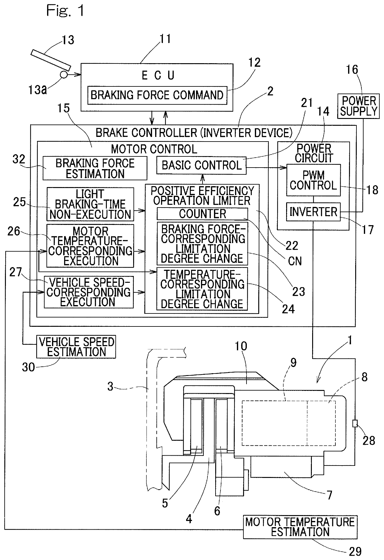
[0033]An electric brake device according to an embodiment of the present invention will be described with reference to the drawings. As shown in FIG. 1, the electric brake device includes: a brake main body 1 that is a mechanical part; and a brake controller 2 that controls the brake main body 1.

[0034]The brake main body 1 includes: a brake rotor 4 that rotates in conjunction with a wheel 3; fixed-side and movable-side friction pads 5 and 6 that come into contact with both surfaces of the brake rotor 4, respectively, to generate a braking force; an electric motor 7; a speed reduction mechanism 8 that reduces a speed of rotation (or number of rotation per unit time) of the motor 7; and a conversion mechanism 9 that converts an output of the speed reduction mechanism 8 into a pressing force of the movable-side friction pad 6. The motor 7 is provided with rotation angle detector (not shown) that detects a rotation angle. The brake rotor 4 is mounted on a hub (not shown) so as to be int...


PUM


Abstract

A brake controller is provided with a positive efficiency operation limiter configured to provide a time for maintaining or decreasing a torque to be generated by a motor, such that a braking force generated by pressing between a brake rotor and friction pads does not decrease, while a braking force command value outputted from a braking force command section increases. For example, the limiter limits a ratio of a time for increasing the braking force, relative to a sum of the time for increasing the braking force and the time for maintaining or decreasing the braking force, to a predetermined value or less.

Description

CROSS REFERENCE TO THE RELATED APPLICATION[0001]This application is a continuation application, under 35 U.S.C. § 111(a), of international application No. PCT / JP2015 / 063181, filed May 7, 2015, which is based on and claims Convention priority to Japanese patent application No. 2014-100290, filed May 14, 2014, the entire disclosure of which is herein incorporated by reference as a part of this application.BACKGROUND OF THE INVENTIONField of the Invention[0002]The present invention relates to an electric brake device provided in an automobile.Description of Related Art[0003]Hitherto, an electric brake actuator using an electric motor, a linear motion mechanism, and a reducer or reduction gear has been proposed (e.g., Patent Document 1). In addition to this, an electric brake that performs deceleration and change into a linear motion with a planetary roller mechanism has also been proposed (Patent Document 2).[0004]A method for using reverse efficiency of an actuator to supply minimum p...

Claims


Application Information

Patent Timeline
Patent Type & Authority Patents(United States)
IPC IPC(8): B60T13/74B60T8/17F16D65/18B60T8/00F16D66/00B60T8/58F16D121/24
CPCB60T13/741B60T8/00B60T8/17B60T8/58B60T13/74F16D65/18F16D66/00F16D2121/24F16D65/183F16D2066/001B60T17/22F16D55/226B60T2250/04
Inventor MASUDA, YUI
Owner NTN CORP
Why Eureka
Try Eureka