Development device

Active Publication Date: 2009-10-15
SHARP KK
View PDF1 Cites 7 Cited by
  • Summary
  • Abstract
  • Description
  • Claims
  • Application Information

AI Technical Summary

Benefits of technology

[0009]In recent years, to deal with printing speed enhancement, color printing and power consumption reduction, in the two-component developer, the particle diameter and softening point of toner have been decreasing and the particle diameter of carrier has been decreasing. Such a two-component developer containing toner and carrier has a problem in that when it is stirred for a long time in the development tank, because of frictional heat and pressure (stress), the external additive on the toner surface is buried in the carrier surface and the wax in the toner adheres to the carrier surface (filming), whereby the fluidity of the two-component developer is readily decreased (deteriorated).
[0010]In particular, in the development device described in Japanese Patent Application Laid-Open No. S62-217275 (1987), if the fluidity of the two-component developer is changed (decreased), since the amount of two-component developer conveyed by the conveyance screw is decreased, it is difficult to make the toner density in the development tank uniform when a multiplicity of document images where the image density is uneven are continuously printed. When the amount of two-component developer conveyed by the conveyance screw is previously set to a slightly larger amount based on a prediction that the fluidity decreases with use, the stress due to the conveyance by the conveyance screw increases and this accelerates the decrease (deterioration) in the fluidity of the two-component developer.
[0011]The present invention is made in view of the above-mentioned circumstances, and an object thereof is to provide a development device capable of suppressing the deterioration of the two-component developer by controlling the amount of conveyance by the tubular developer conveyance path in the development tank according to the condition, characteristic and the like of the two-component developer in the development tank, and uniformizing the toner density of the two-component developer in the development tank even when the two-component developer is deteriorated.

Problems solved by technology

Such a two-component developer containing toner and carrier has a problem in that when it is stirred for a long time in the development tank, because of frictional heat and pressure (stress), the external additive on the toner surface is buried in the carrier surface and the wax in the toner adheres to the carrier surface (filming), whereby the fluidity of the two-component developer is readily decreased (deteriorated).
S62-217275 (1987), if the fluidity of the two-component developer is changed (decreased), since the amount of two-component developer conveyed by the conveyance screw is decreased, it is difficult to make the toner density in the development tank uniform when a multiplicity of document images where the image density is uneven are continuously printed.

Method used


Image

  • Development device
  • Development device
  • Development device

Examples


first embodiment

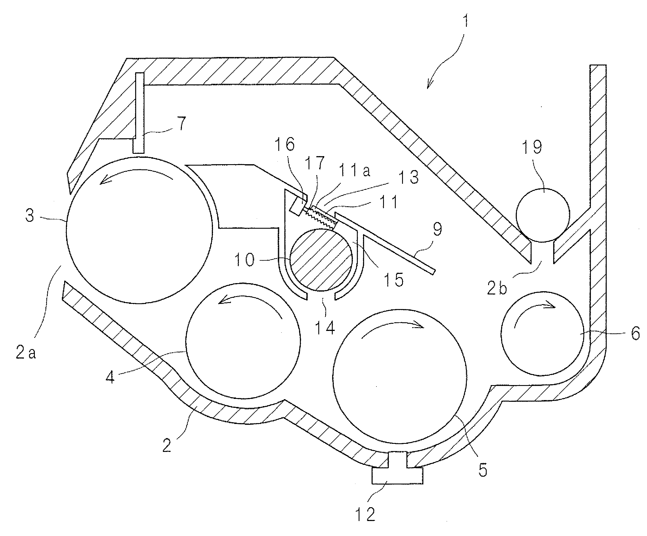
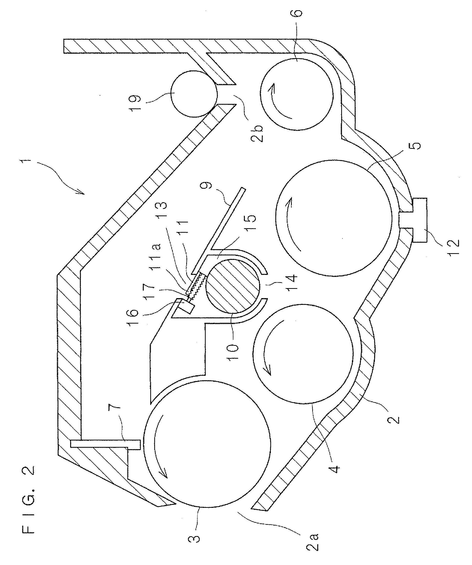
[0059]Next, the development device 1 according to the present invention will be described. FIGS. 2 and 3 are front cross-sectional views showing the structure of the development device 1. FIG. 2 shows a condition where the area of the opening of a developer supply mouth is minimum. FIG. 3 shows a condition where the area of the opening of the developer supply mouth is maximum. FIG. 4 is a cross-sectional view taken along line IV-IV of FIG. 3. FIGS. 5 and 6 are top plan views showing the inside of a development tank in a condition where the upper lid of the development tank is removed. FIG. 5 shows a condition where the area of the opening of the developer supply mouth is minimum. FIG. 6 shows a condition where the area of the developer supply opening is maximum. FIGS. 7A and 7B are bottom plan views of a flow plate in FIGS. 5 and 6 viewed from the bottom side. FIG. 7A corresponds to FIG. 5, and FIG. 7B corresponds to FIG. 6.

[0060]The development device 1 according to the present inv...

second embodiment

[0080]FIGS. 10 and 11 are front cross-sectional views showing the structure of a development device 1A according to the A piezoelectric sensor 18 is attached to the bottom surface, on the end opposite to the development roller 3, of the flow plate 9. When the fluidity of a two-component developer G is high (excellent), since the two-component developer G is smoothly conveyed in the development tank 2, it is not very high in bulk and does not touch the piezoelectric sensor 18 (the condition of FIG. 10). When the fluidity of the two-component developer G is low (inferior), the two-component developer G is high in bulk in the development tank 2 and touches the piezoelectric sensor 18 (the condition of FIG. 11). Since the detection signal of the piezoelectric sensor 18 differs between the condition where the two-component developer G touches and the condition where it does not touch, whether the fluidity of the two-component developer G is high or low can be detected by the piezoelectr...


PUM


Abstract

A development device is provided with: a development roller that rotates while carrying a two-component developer in a development tank accommodating the two-component developer; a tubular developer conveyance path having therein a conveyance mechanism that conveys the two-component developer in an axial direction of the development roller; a developer supply mouth for supplying the two-component developer to the developer conveyance path; a developer discharge mouth for discharging the two-component developer from the developer conveyance path; a supply mouth adjustment member that adjusts the area of the opening of the developer supply mouth; and a control unit that causes the supply mouth adjustment member to operate based on the fluidity of the two-component developer in the development tank.

Description

CROSS-REFERENCE TO RELATED APPLICATIONS[0001]This Nonprovisional application claims priority under 35 U.S.C. §119(a) on Patent Application No. 2008-103806 filed in Japan on Apr. 11, 2008, the entire contents of which are hereby incorporated by reference.BACKGROUND OF THE INVENTION[0002]1. Technical Field[0003]The present invention relates to a development device using a two-component developer, more specifically, to a development device that develops an electrostatic latent image on a latent image carrier such as a photoconductor drum by supplying a two-component developer thereto.[0004]2. Description of Related Art[0005]In an image forming apparatus using electrostatic electrophotography, generally, steps of charging, exposure, development, image transfer, cleaning, charge removal and fixing are continuously performed. In such an electrostatic electrophotographic image forming apparatus, in forming an image, for example, the surface of a photoconductor drum being rotated is uniform...

Claims


Application Information

Patent Timeline
IPC IPC(8): G03G15/08
CPCG03G15/0848G03G15/0877G03G15/0891G03G2215/0634
Inventor HAYASHI, SHIGEKI
Owner SHARP KK
Why Eureka
Try Eureka