Development device and image forming apparatus provided therewith

Active Publication Date: 2012-02-23
SHARP KK
View PDF6 Cites 11 Cited by
  • Summary
  • Abstract
  • Description
  • Claims
  • Application Information

AI Technical Summary

Benefits of technology

[0009]An object of the present invention is to provide a development device that can suppress the rapid pressure rise of the developer during the circulating conveyance to reduce the stress applied to the developer and suppress the lowering of the image density and an image forming apparatus provided with the development device.
[0022]According to the development device of the present invention, for example, when the end blade is provided on an upstream side of the first developer conveying spiral member, the developer that is conveyed and deposited on a downstream side in the second developer conveying path by the second developer conveying spiral member is raked in the first developer conveying path by the circumferential agitating plate portion of the rotating end blade of the first developer conveying spiral member, and the developer is conveyed onto the downstream side by the spiral blade portion. Therefore, the pressure, to which the developer conveyed to a most downstream of the second developer conveying path is subjected when pressed against the downstream inside wall surface of the developer tank, can be relaxed to reduce the stress. As a result, while the decrease in developer fluidity is reduced, the developer in the first developer conveying path side can smoothly move to the second developer conveying path without remaining the developer on the downstream side of the first developer conveying path. The same holds true for the case in which the second developer conveying spiral member includes the end blade on the upstream side.
[0023]When the end blade is provided on the downstream side of the first developer conveying spiral member, in the developer conveyed onto the downstream side of the first developer conveying path by the first developer conveying spiral member, an agitating force is applied to the circumferential direction of the rotary shaft by the circumferential agitating plate in addition to a force in the conveying direction by the spiral blade portion of the end blade, and therefore the developer is raked onto the second developer conveying path side. Therefore, the pressure, to which the developer conveyed to the most downstream of the first developer conveying path is subjected when pressed against the downstream inside wall surface of the developer tank, can be relaxed to reduce the stress. As a result, while the decrease in developer fluidity is reduced, the developer in the second developer conveying path side can smoothly move to the first developer conveying path without remaining on the downstream side of the second developer conveying path. The same holds true for the case in which the second developer conveying spiral member includes the end blade on the downstream side.
[0024]When each of the first and second developer conveying spiral members includes the end blades at both ends of the rotary shaft, while the decrease in developer fluidity is reduced, the developer can smoothly move in the circulating manner in the first and second developer conveying paths without remaining. Therefore, according to the image forming apparatus of the present invention provided with the development device, the developer is smoothly circulated between the first developer conveying path and the second developer conveying path, and the sufficient amount of developer is supplied to the photoconductive drum through the development roller, so that the image can be printed on the recording medium with the sufficient image density.

Problems solved by technology

As a result, the sufficient amount of developer is hardly supplied to the photoconductive drum through the development roller, and unfortunately density of an image printed in a recording medium is lowered.

Method used


Image

  • Development device and image forming apparatus provided therewith
  • Development device and image forming apparatus provided therewith
  • Development device and image forming apparatus provided therewith

Examples


first embodiment

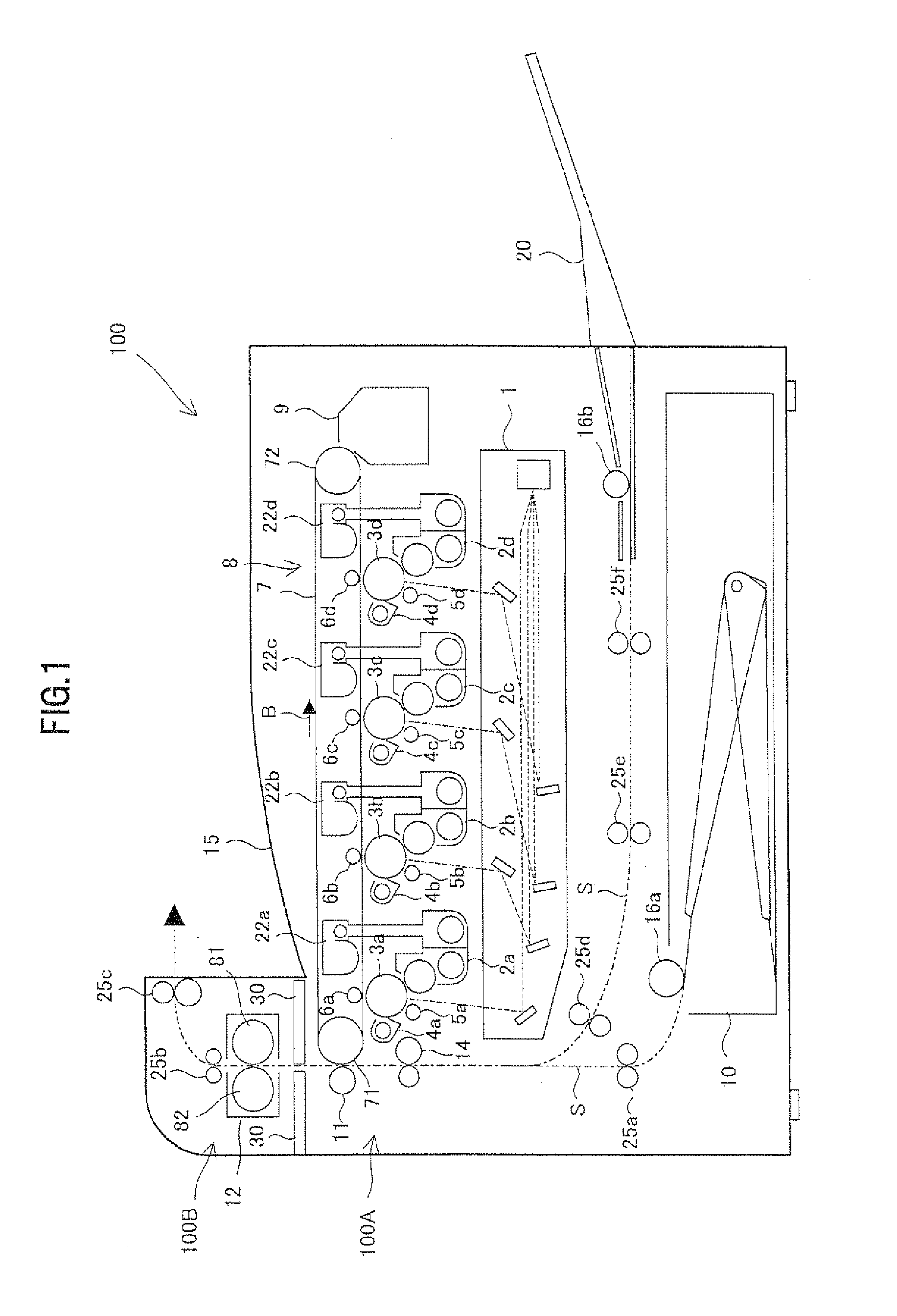
[0049]FIG. 1 illustrates an entire configuration of an image forming apparatus provided with a development device according to a first embodiment of the present invention. An image forming apparatus 100 of the first embodiment is a printer including a development device housing 100A in which plural development devices 2a to 2d are accommodated in a casing, a fusing device housing 100B in which a fusing device 12 is accommodated in a casing above the development device housing 100A, and a partition wall 30 that performs heat insulation such that heat of the fusing device 12 does not transfer onto the development device side. The image forming apparatus 100 can form a multi-color or monochrome image in a sheet-like recording medium (recording paper) according to externally-transmitted image data. An upper surface of the development device housing 100A, which is located lateral to the fusing device housing 100B, constitutes a sheet exit tray 15.

[0050]In the first embodiment, the printe...

second embodiment

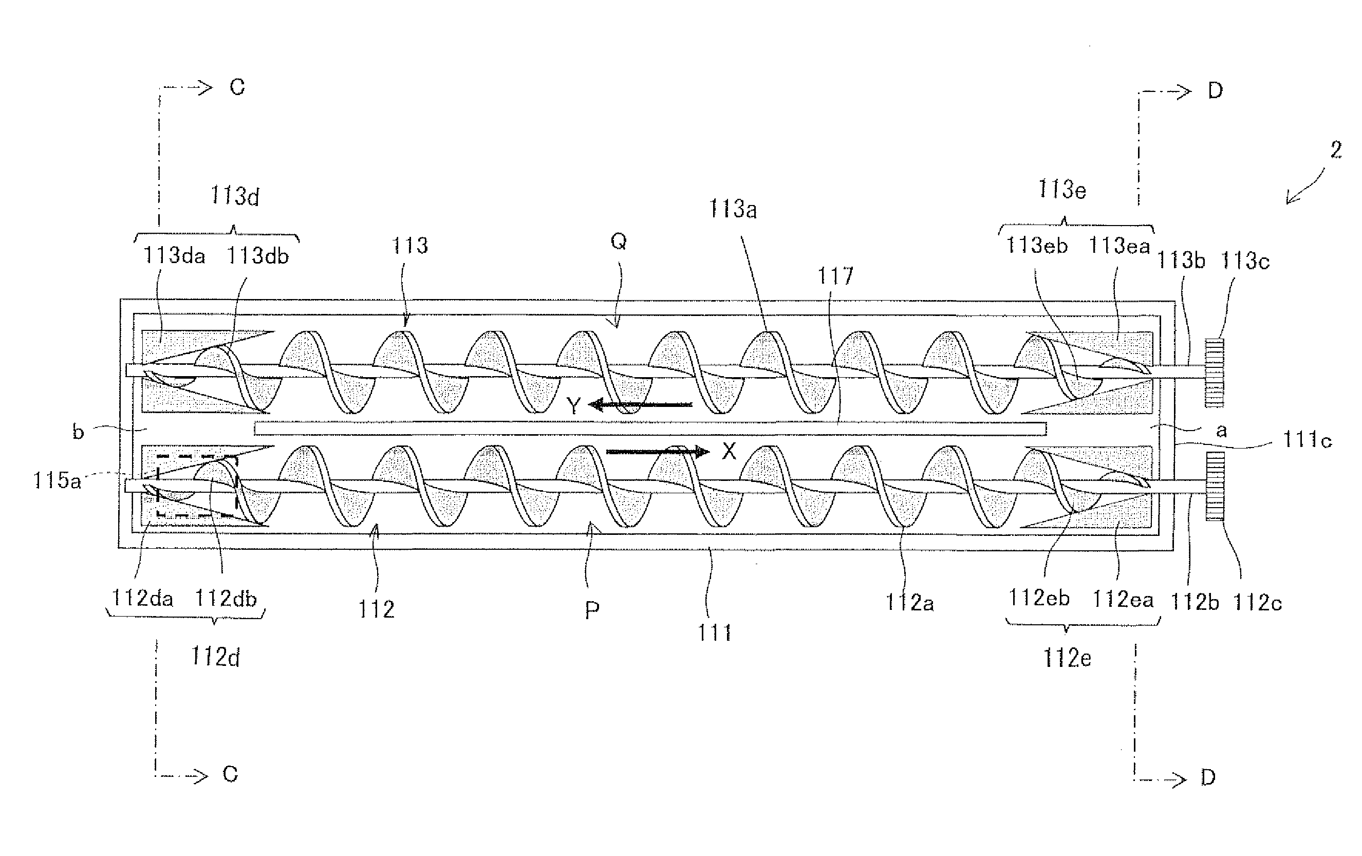
[0122]FIG. 13 is a horizontal sectional view illustrating a development device according to a second embodiment of the present invention. In FIG. 13, the same component as that of FIG. 3 is designated by the same numeral. A development device 2X of the second embodiment differs from the development device 2 of the first embodiment in that the downstream end blades 112e and 113d (see FIG. 3) of the first and second developer conveying spiral members 112 and 113 in the first embodiment are omitted and that downstream ends of the spiral blades 112a and 113a are extended to neighborhoods of both the sidewalls in the longitudinal direction of the developer tank 111. Other configurations of the second embodiment are similar to those of the first embodiment. For the development device 2X, the first and second developer conveying spiral members 212 and 213 do not have the downstream end blades. However, the developers conveyed onto the downstream sides of the first and second developer conv...

third embodiment

[0123]FIG. 14 is a horizontal sectional view illustrating a development device according to a third embodiment of the present invention. In FIG. 14, the same component as that of FIG. 13 is designated by the same numeral. A development device 2Y of the third embodiment resembles the development device 2X of the second embodiment. However, the development device 2Y of the third embodiment differs from the development device 2X of the second embodiment in the shapes of upstream end blades 312d and 313e of first and second developer conveying spiral members 312 and 313, other configurations are similar to those of the second embodiment. In the first developer conveying spiral member 312, the upstream end blade 312d is disposed opposite the second communicating path “b”, and the upstream end blade 312d includes a below-described spiral blade portion 312db and a below-described circumferential agitating plate portion 312da.

[0124]The spiral blade portion 312db has the same constant diame...


PUM


Abstract

A development device mounted on an electrophotographic image forming apparatus including a photoconductive drum in which an electrostatic latent image is formed on a surface thereof, the development device comprising: a developer tank; a development roller that is provided in the developer tank; first and second developer conveying paths; and first and second developer conveying spiral members that conveying the developer in the circulating manner in the first and second developer conveying paths, wherein at least one of the first and second developer conveying spiral members further includes an end blade that is provided at one end of the rotary shaft, the end blade includes: a spiral blade portion that is fixed to the circumferential surface of the rotary shaft; and a circumferential agitating plate portion that is fixed to a circumferential portion of the spiral blade portion.

Description

CROSS-REFERENCE TO RELATED APPLICATION[0001]This application is related to Japanese patent application No. 2010-186310 filed on Aug. 23, 2010 whose priority is claimed under 35 USC §119, the disclosure of which is incorporated by reference in its entirety.BACKGROUND OF THE INVENTION[0002]1. Field of the Invention[0003]The present invention relates to a development device in which a dual-component developer is used and an image forming apparatus provided with the development device.[0004]2. Description of the Related Art[0005]In recent years, for electrophotographic image forming apparatuses supporting full-color and high-quality images, a dual-component developer (hereinafter simply referred to as the “developer”) which exhibits an excellent charge performance stability as to a toner is in widespread use. The developer is made up of the toner and a carrier, which are agitated in a development device and frictionally rubbed with each other to produce an appropriately electrified tone...

Claims


Application Information

Patent Timeline
IPC IPC(8): G03G15/08
CPCG03G2215/0838G03G15/0822
Inventor MIHARA, KOICHINAGAI, TAKAFUMI
Owner SHARP KK
Why Eureka
Try Eureka