Latch device

Active Publication Date: 2009-10-22
ILLINOIS TOOL WORKS INC
View PDF21 Cites 9 Cited by
  • Summary
  • Abstract
  • Description
  • Claims
  • Application Information

AI Technical Summary

Benefits of technology

[0007]The present invention provides advantages and alternatives relative to prior known latch assemblies by providing a latch device including a latch strike retention assembly adapted for press-fit insertion into a panel opening and retention within the panel opening upon melting of any plastic components. The latch strike retention assembly includes a generally “U” shaped spring member having spring legs operatively connected to bushings arranged in converging opposing relation to one another and adapted to engage and retain a strike member disposed in opposing relation to the strike retention assembly. The spring member is held within a bracket member of substantially “U” shaped cross section. The bracket member is disposed in transverse orientation to the spring member.
[0008]According to one exemplary aspect, the present invention provides a latch strike retention assembly adapted to accept and retain a latch strike. The latch strike retention assembly includes a bracket member of substantially “U” shaped profile adapted for retention within a panel opening. The bracket member includes a bracket base and a pair of substantially opposing bracket legs extending away from the bracket base. An anchor latch is disposed at the interior of the bracket member, the anchor latch includes a substantially “U” shaped spring member. The spring member includes a first spring leg extending away from a spring base and at least a second spring leg extending away from the spring base. The first spring leg operatively engages a first bushing structure and the second spring leg operatively engages a second bushing structure. The first bushing structure and the second bushing structure are disposed in opposing relation to one another and cooperatively define a strike acceptance crevice having a length dimension extending between the first bushing structure and the second bushing structure. The anchor latch is secured at an interior portion of the bracket member with the spring member oriented transverse to the bracket member with the length dimension of the strike acceptance crevice oriented transverse to the bracket legs.
[0009]According to another exemplary aspect, the present invention provides a latch strike retention assembly adapted to accept and retain a latch strike. The latch strike retention assembly includes a bracket member of substantially “U” shaped profile adapted for retention within a panel opening. The bracket member includes a bracket base, a first bracket leg extending away from the bracket base and a second bracket leg extending away from the bracket base. An anchor latch is disposed at the interior of the bracket member. The anchor latch includes a substantially “U” shaped spring member, the spring member includes a first spring leg extending away from a spring base and at least a second spring leg extending away from the spring base. The first spring leg operatively engages a first bushing structure and the second spring leg operatively engages a second bushing structure. The first bushing structure and the second bushing structure are disposed in op

Problems solved by technology

While the device described in U.S. Pat. No. 4,272,111 operates in a satisfactory manner, the inclusion of the blocking legs as part of the spring necessitates a relatively high insertion force when the latch assembly is originally installed.
Thus, the blocking legs projecting from the spring may experience corresponding movement and a resultant degree of wear over time.

Method used


Image

  • Latch device
  • Latch device
  • Latch device

Examples


Embodiment Construction

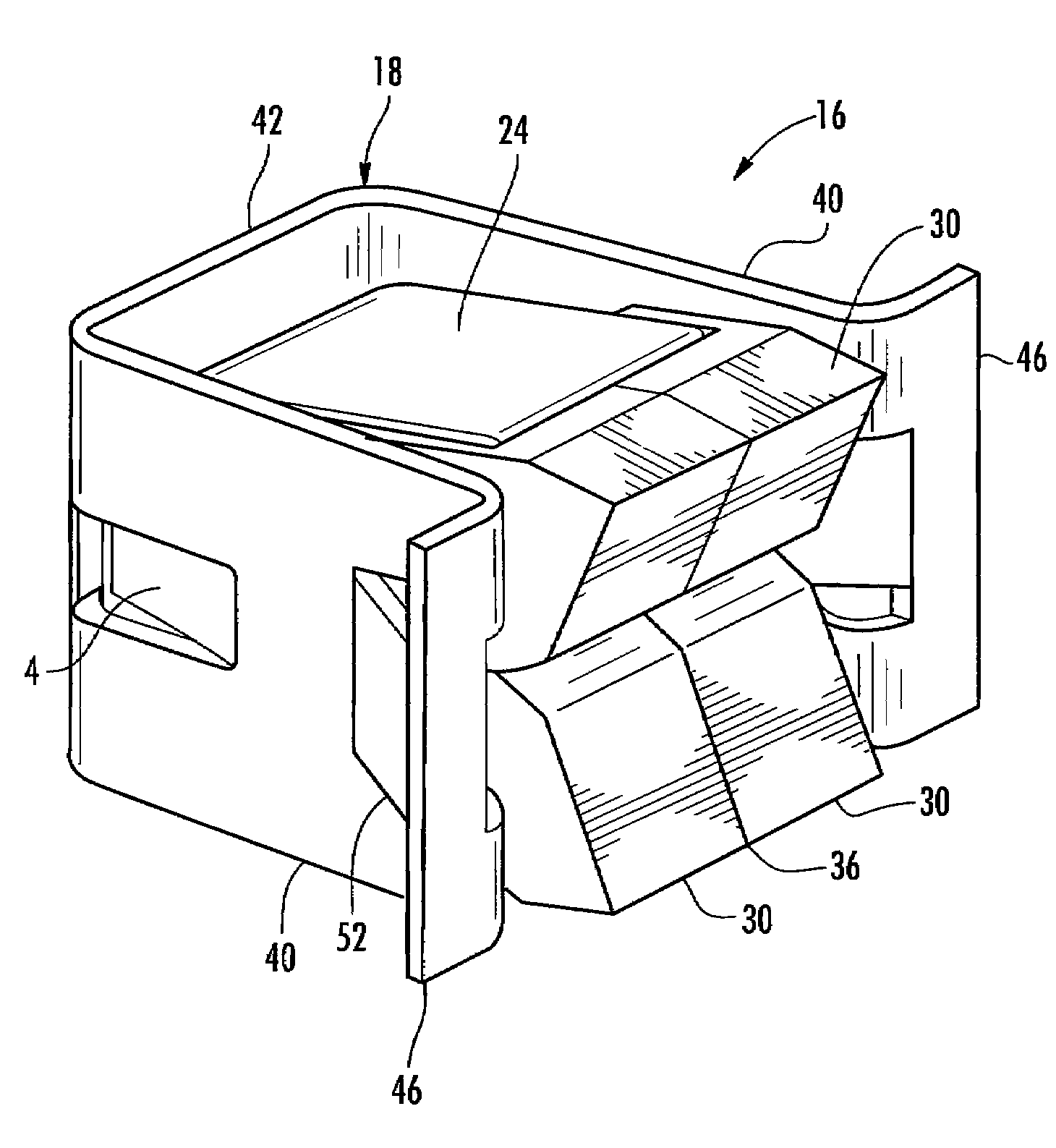
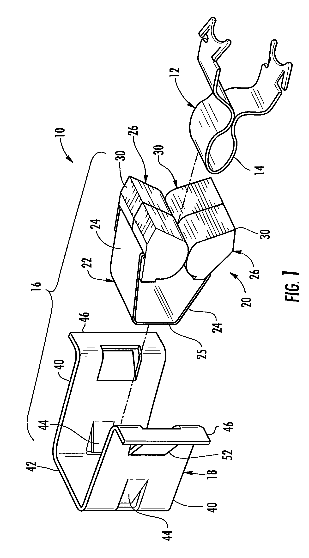
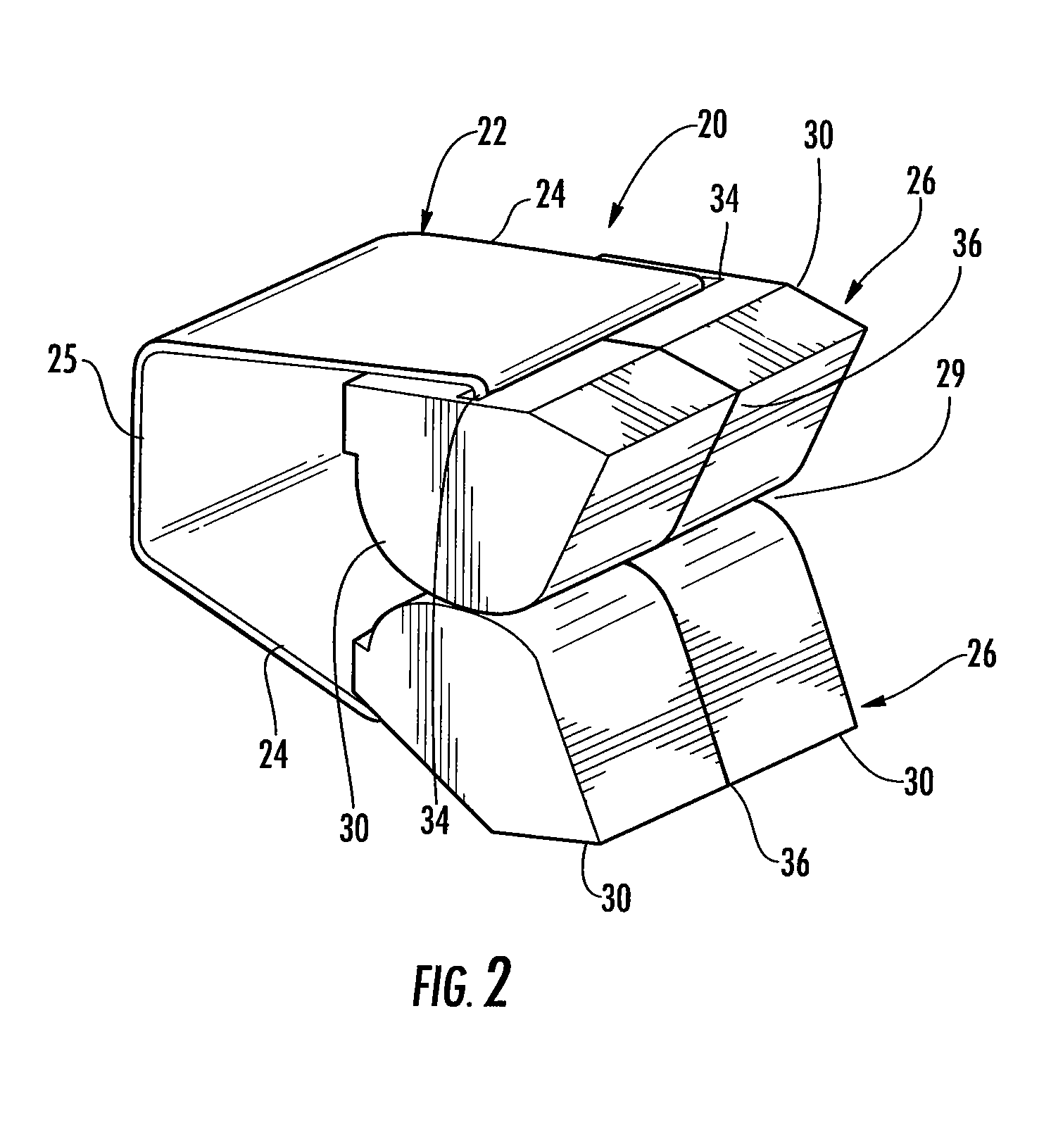
[0017]Reference will now be made to the drawings, wherein like reference numerals are utilized to designate like elements in the various views. FIG. 1 is an exploded perspective view of a latch assembly 10. As shown, the latch assembly 10 includes a strike 12 which may be held in secure relation within a first structure such as an appliance cabinet or the like (not shown). The strike 12 includes a bulbous head portion 14 adapted to project outwardly away from the structure supporting the strike 12. The latch assembly 10 further includes a strike retention assembly 16 as illustrated in FIGS. 1 and 3, incorporating a bracket member 18 and a spring-biased anchor latch 20. As may be seen through joint reference to FIGS. 1, 2, and 3, the anchor latch 20 is held in substantially nested relation at the interior of the bracket member 18 upon final assembly to form the strike retention assembly 16. The strike retention assembly 16 is normally housed within a door panel or other support struc...


PUM


Abstract

A latch device including a latch strike retention assembly adapted for press-fit insertion into a panel opening and retention within the panel opening upon melting of any plastic components. The latch strike retention assembly includes a generally “U” shaped spring member having spring legs operatively connected to bushings arranged in converging opposing relation to one another and adapted to engage and retain a strike member disposed in opposing relation to the strike retention assembly. The spring member is held within a bracket member of substantially “U” shaped cross section. The bracket member is disposed in transverse orientation to the spring member.

Description

CROSS-REFERENCE TO RELATED APPLICATIONS[0001]This application claims the benefit of, and priority from, U.S. Provisional Application 61 / 045,681 filed Apr. 17, 2008, the contents of which are incorporated herein by reference in their entirety.TECHNICAL FIELD[0002]The present invention relates generally to latches, and, more particularly, to latches used in containment structures and appliances such as dryers and the like to hold a containment door in closed position relative to a containment cabinet.BACKGROUND OF THE INVENTION[0003]In many containment structures including appliances such as dryers and the like, a door may be held in a closed position by a latching assembly incorporating a retainer in combination with a latch pin or strike. The retainer is typically snapped into a punched out hole in the door and the strike is positioned in opposing relation within the associated cabinet. Once the door is closed, the head of the strike is trapped within the retainer until an opening f...

Claims


Application Information

Patent Timeline
IPC IPC(8): A44B21/00A44B99/00
CPCE05C19/063Y10T24/44026Y10S292/69Y10T292/685Y10T292/0817
Inventor MORGAN, KARL S.DAM, ROBERTDAVIS, MIKE
Owner ILLINOIS TOOL WORKS INC
Why Eureka
Try Eureka