Rifle scope installation fixture and method of use

a technology for installing fixtures and scopes, applied in the direction of weapons, weapon cleaning, ammunition loading, etc., can solve the problems of vises affecting the rifle, the fixing is adapted, and the installation of the scope is not complete, so as to facilitate the attachment of the scope

Active Publication Date: 2012-11-27
HOLLAND DARRELL
View PDF30 Cites 18 Cited by
  • Summary
  • Abstract
  • Description
  • Claims
  • Application Information

AI Technical Summary

Benefits of technology

[0006]In a second separate aspect, the present invention is a fixture for facilitating the attachment of a scope to a rifle, with a minimum of misalignment between the vertical line of the scope reticle and the direction of bullet drop, which is determined by gravity. The fixture includes a rifle vise, including a bottom wall, extending at least 6 cm in a longitudinal dimension, a side wall extending at least 6 cm in the longitudinal dimension, a support and a threaded aperture structure supported by the suppor

Problems solved by technology

Despite this need, there appears to be no fixture adapted to facilitating scope installation so that this requirement is met.
Unfortunately, maintaining this orientation until scope installation is complete is problematic.
Cradles normally don't provide a means of securing the rifle in the proper position, and vises can disturb the rifle as they are tightened.
These shortcomings frequently result in the expenditure of time and energy, as multiple attempts to maintain and verify the rifl

Method used


Image

  • Rifle scope installation fixture and method of use
  • Rifle scope installation fixture and method of use
  • Rifle scope installation fixture and method of use

Examples


Embodiment Construction

)

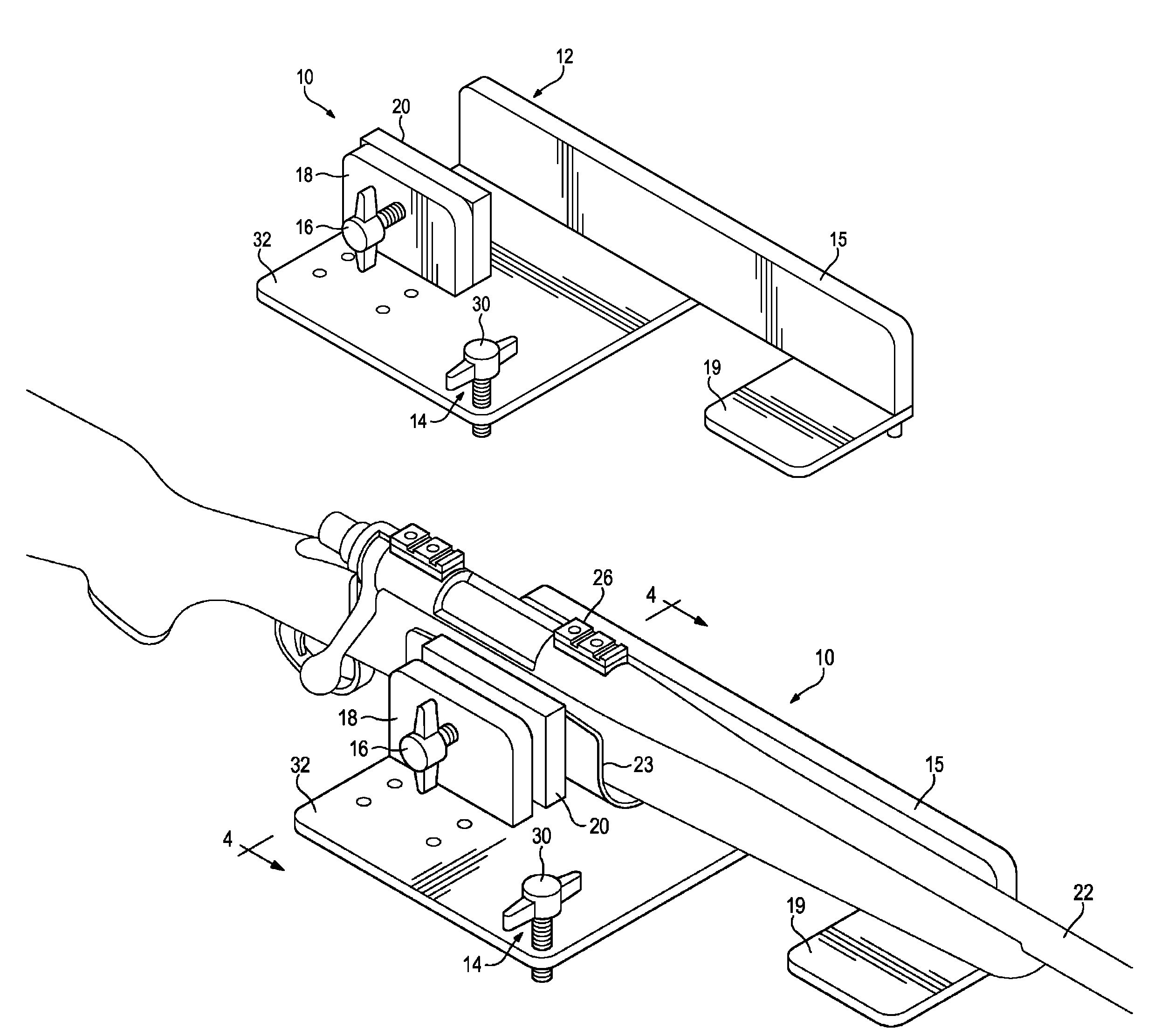
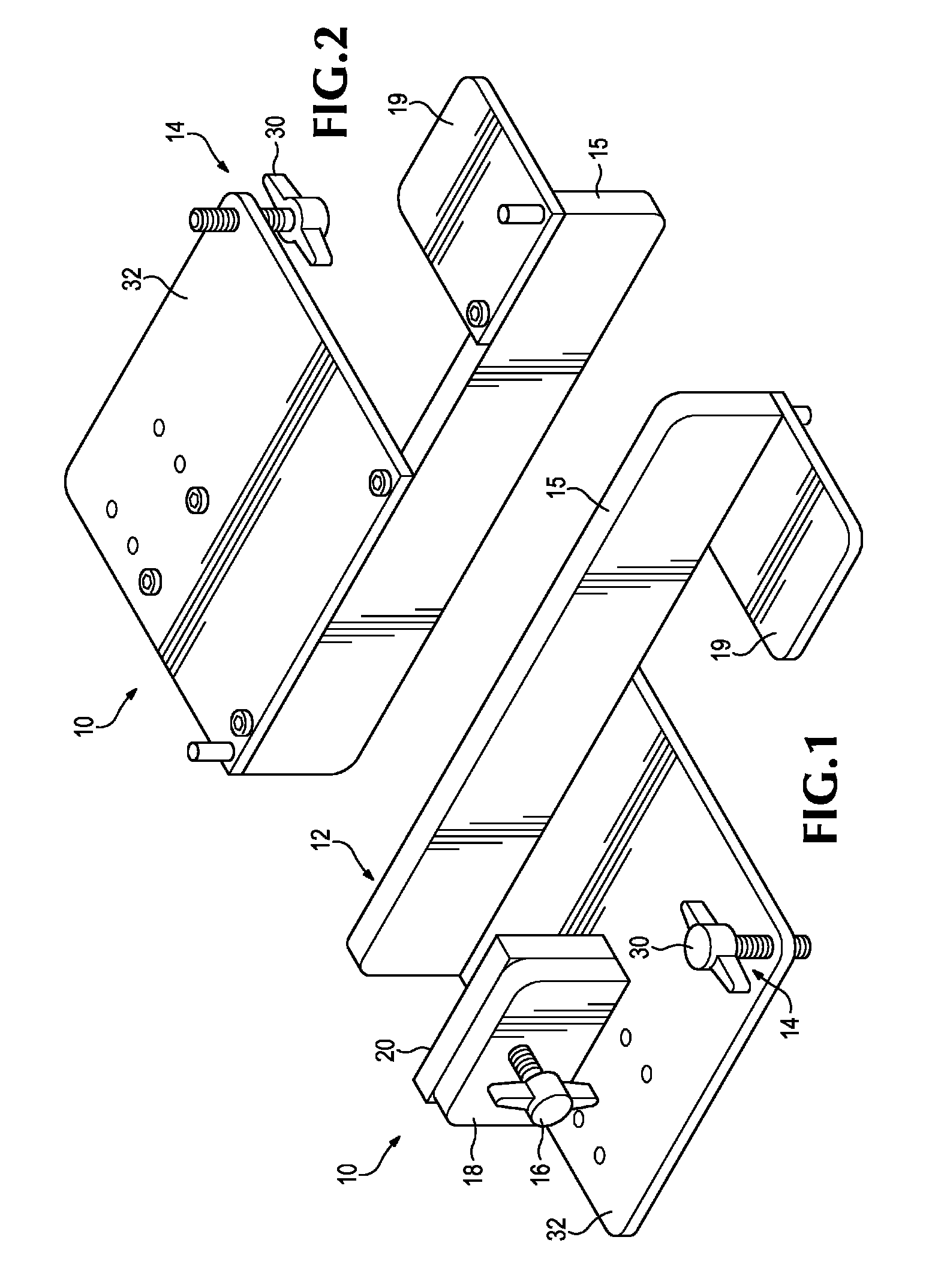
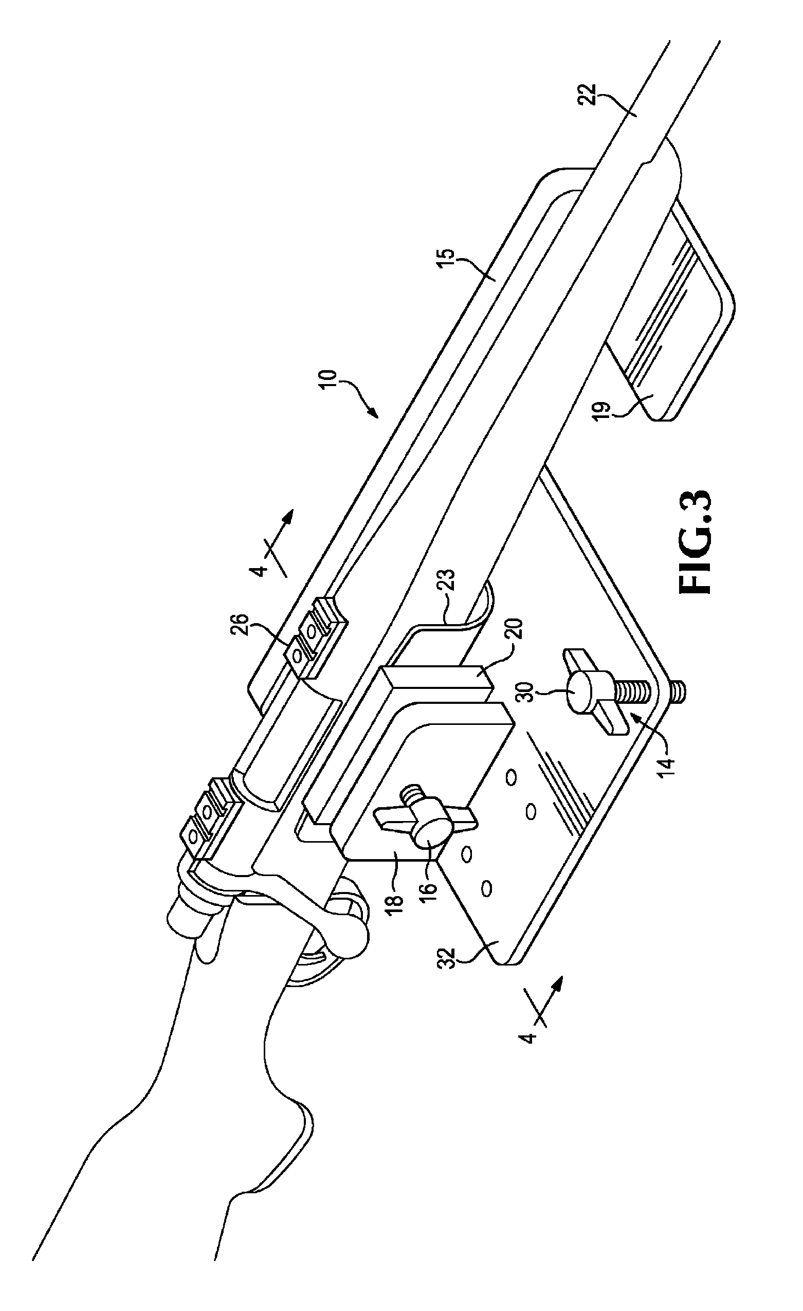
[0013]Referring to FIG. 1, a preferred embodiment of a scope-mounting facilitating fixture 10, according to the present invention, includes a rifle vise 12 and a rifle vise angle adjust 14. Vise 12 includes a side wall 15, a bottom wall 17, a forward rifle stock rest 19, and a threaded bolt 16 fit into a threaded aperture defined in a support 18 that is anchored to bottom wall 17. Bolt 16 when rotated so that it moves inwardly, presses against a block 20, which presses a rifle 22 (FIG. 3) against side wall 15, securely clamping rifle 22 in place. In a preferred embodiment bolt 16 engages with a divot (not shown) defined in the surface of block 20. A flexible sheet 23 (FIG. 4), such as a cloth or a polymeric foam web may be used in vise 12 to prevent damage to the stock of rifle 22. Block 20 can be made of tough but resiliently compressible material, so that it can deform slightly to conform to the shape of the side of a rifle, thereby creating a better grip, but not be damaged in t...


PUM


Abstract

A method of installing a rifle scope to a rifle such that when the rifle is transversely level, the vertical line of the scope reticle is aligned with the direction of bullet drop. The method uses a mounting facilitating fixture having a rifle vice and a rifle vice transverse orientation adjustment device. First, the rifle is clamped into the rifle vice and the rifle vice transverse orientation adjustment device is adjusted until the rifle is transversely level. Then, while the rifle is still held in a transversely level position in the rifle vice, a scope having a vertical line in the reticle is connected to the rifle so that the vertical line is plumb in relation to the Earth. Because both the direction of bullet drop and the vertical line of the scope reticle are aligned with gravity, they are aligned with each other.

Description

BACKGROUND[0001]It is very important that a rifle scope be installed on a rifle so that when the rifle is level, the vertical line of the scope reticle is aligned plumb (i.e., perpendicular) relative to the Earth. This relationship ensures that when the scope's elevation dial is adjusted the resultant changes in bullet impact points will coincide with the direction of bullet drop, which is determined by gravity. If the scope is installed such that when the rifle is level the vertical line of the scope reticle does not mirror the direction of bullet drop, a windage (or horizontal) error is progressively introduced as the scope's elevation dial is adjusted for greater bullet drop. Despite this need, there appears to be no fixture adapted to facilitating scope installation so that this requirement is met.[0002]During scope installation, a rifle is typically placed in a cradle or vise. Ideally, the rifle is oriented so that the top of the receiver (or the scope base attached thereto) is...

Claims


Application Information

Patent Timeline
IPC IPC(8): F41A23/16
CPCF41A23/16F41G11/001
Inventor HOLLAND, DARRELL
Owner HOLLAND DARRELL
Why Eureka
Try Eureka