
Flat panel display

a technology for flat panels and displays, applied in the field of flat panel displays, can solve the problems of long time-consuming design changes and increased costs, and achieve the effect of improving ease of assembling work

Inactive Publication Date: 2009-10-22
FUNAI ELECTRIC CO LTD
View PDF2 Cites 21 Cited by
  • Summary
  • Abstract
  • Description
  • Claims
  • Application Information

AI Technical Summary

Benefits of technology

[0019]The locating members hold the side surfaces forming the corners of the display panel to locate the display panel and are fastened to the front cabinet with the screws. Therefore, only the locating members need to be changed and any changes in the front cabinet are unnecessary to deal with the change of the shape of the display panel. Since the display panel is fixed to the front cabinet after locating the corners of the display panel, any comparatively large fixing members are unnecessary and materials can be reduced to reduce the cost.
[0030]According to the present invention, fastening directions in which the screws exert fastening force are uniform and hence ease of assembling work can be improved.

Problems solved by technology

Design change takes a long time and increases the cost.

Method used


Image

  • Flat panel display
  • Flat panel display
  • Flat panel display

Examples


first embodiment

1. First Embodiment

2. Second Embodiment

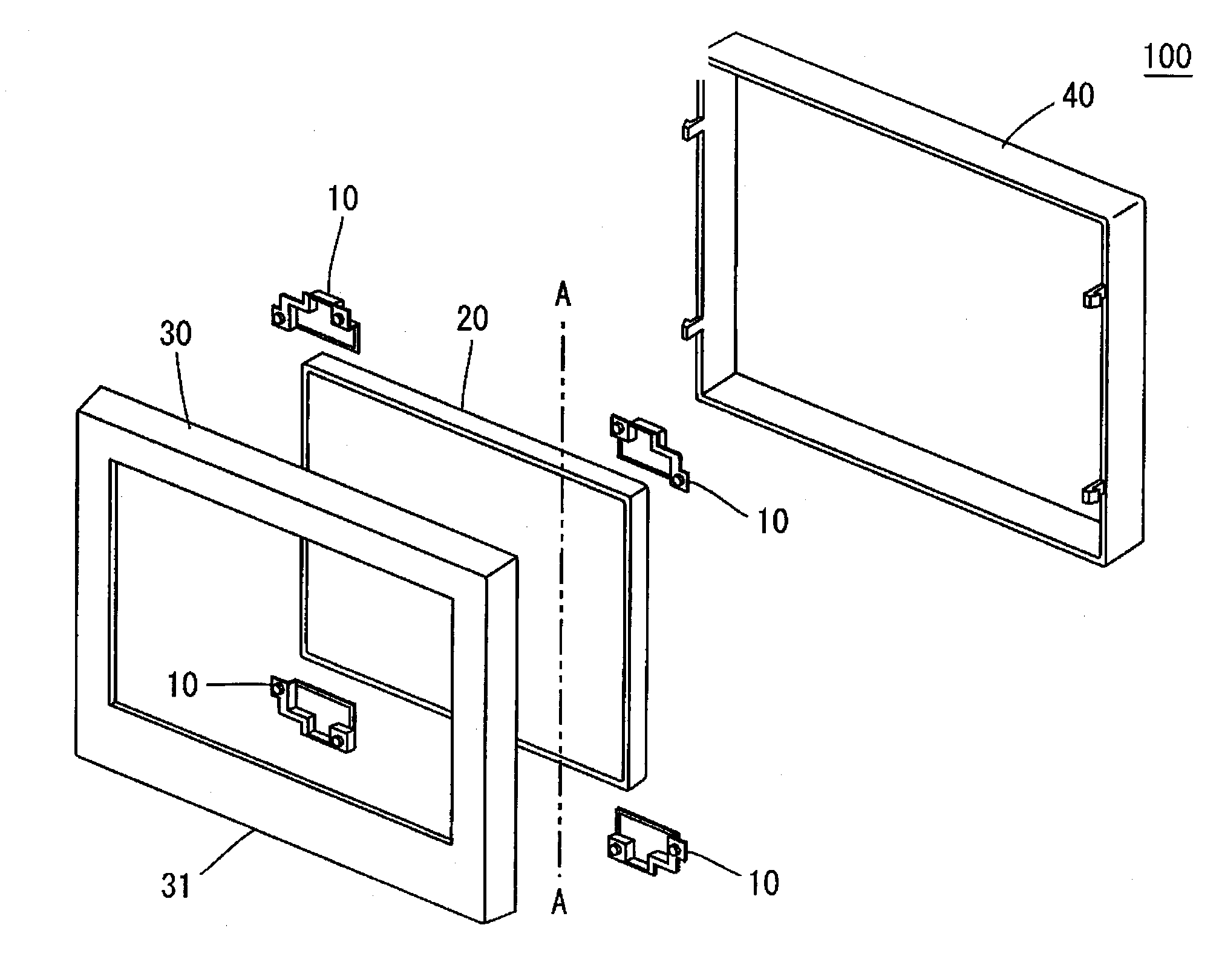
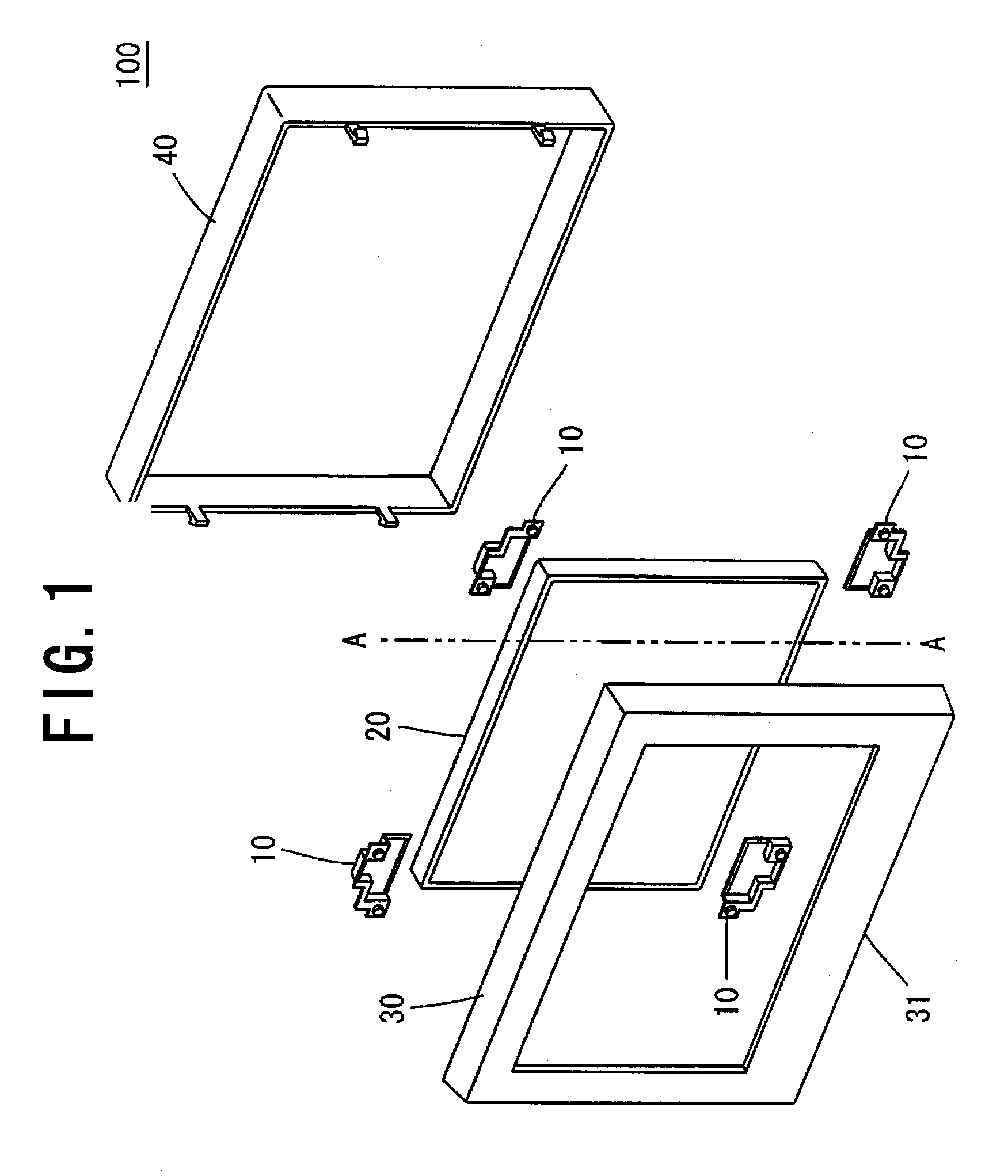
[0046]FIG. 1 is an exploded perspective view of a flat panel display 100 in a first embodiment according to the present invention. The flat panel display 100 includes a substantially rectangular display panel 20 capable of displaying images, a front cabinet 30 forming a front part of a cabinet for holding the display panel 20 therein, and a rear cabinet 40 forming a rear part of the cabinet.

[0047]The flat panel display 100 is assembled by putting the display panel 20 in the front cabinet 30 through the open rear end 31 of the front cabinet 30 and fixing the display panel 20 to the front cabinet 30, and then fixedly joining the rear cabinet 40 to the front cabinet 30 so as to cover the open rear end 31 of the front cabinet 30. The display panel 20 is fixed to the front panel 30 after being positioned on the front cabinet 30 by locating members 10. A driving board, not shown, for driving the display panel 20 is attached to the back surface of the...

second embodiment

2. Second Embodiment

[0075]The first embodiment uses the locating members 10 for locating the display panel 20 on the front cabinet 30. The locating members 10 may be used for fixing the display panel 20 to the front cabinet 30. When the display panel 20 is a small one, such as a 15 in. display panel, the display panel 20 has a small weight. Such a light display panel 20 can be satisfactorily fixed to the front cabinet 30 only by the locating members 10.

[0076]FIG. 13 is a rear view of a front cabinet 30 in a modification and a display panel 20 fixed to the front cabinet 30. Since diagonally opposite corners of the display panel 20 are located on and fixed to the front cabinet 30 by locating members 10, parts like the first bosses 35 and the screws for fixing the display panel 30 to the front cabinet 30 are not necessary and work for assembling a flat panel display 100 can be reduced. Consequently, time for assembling the flat panel display 100 can be curtailed.

[0077]While the inventi...


PUM


Abstract

A flat panel display includes locating members each having a plate-shaped base part, a holding surface rising substantially perpendicularly from sides forming a corner of the base part, and a flange extending outward from the skirt of the holding surface and provided with through holes. The locating members are disposed with the base parts thereof facing a back surface of a display panel and the holding surfaces pressed against side surfaces forming corners of the display panel. Screws passed through the through holes are screwed into the internally threaded holes of bosses to locate the display panel on a front cabinet. The specifications of the display panel can be changed without changing the design of the front cabinet.

Description

[0001]The entire disclosure of Japan Patent Application No. 2008-108189, filed Apr. 17, 2008, is expressly incorporated by reference herein.BACKGROUND OF THE INVENTION[0002]1. Field of the Invention[0003]The present invention relates to a flat panel display assembled by fixedly placing a substantially rectangular display panel in a box-shaped front cabinet having a predetermined side provided with an opening, and fixing a rear cabinet to the front cabinet so as to cover the opening.[0004]2. Description of the Related Art[0005]There is a known flat panel display built by fixedly holding a display panel in a box having a front cabinet and a rear cabinet. This known flat panel display is assembled by putting the display panel in the front cabinet through the predetermined opening formed in the front cabinet, fixing the display panel to the front cabinet, and fixing the rear cabinet to the front cabinet so as to cover the opening. The display panel is attached to the front cabinet by fi...

Claims


Application Information

Patent Timeline
Patent Type & Authority Applications(United States)
IPC IPC(8): A47B81/06
CPCG02F1/133308G02F2001/133322H04N5/64G06F2200/1612G06F1/1601G02F1/133322
Inventor YAMANAKA, TAKAHITO
Owner FUNAI ELECTRIC CO LTD
Learn More