Inkjet printer system and ink supply apparatus

a printer system and ink supply technology, applied in printing and other directions, can solve the problems of large amount of ink consumed in a relatively short time, dripping problem, and inability to properly discharge ink,

Active Publication Date: 2009-10-22
MIMAKI ENG
View PDF8 Cites 5 Cited by
  • Summary
  • Abstract
  • Description
  • Claims
  • Application Information

AI Technical Summary

Benefits of technology

[0008]According to one aspect of the present invention, an inkjet printer system includes a print head and a sub tank. The print head is configured to eject ink. The sub tank is provided above the print head and connected to the print head via a head-side supply passage. The sub tank has a first supplying hole and a second supplying hole which are connected to the head-side supply passage. A position of the first supplying hole is higher than a position of the second supplying hole.
[0009]According to another aspect of the present invention, an ink supply apparatus includes a sub tank. The sub tank is provided above a print head of an inkjet printer system and connected to the print head via a head-side supply passage. The sub tank has a first supplying hole and a second supplying hole which are connected to the head-side supply passage. A position of the first supplying hole is higher than a position of the second supplying hole.

Problems solved by technology

In case of a large-sized inkjet printer for printing commercial advertisements, banners, and the like, a large amount of ink is consumed in a relatively-short time.
As the inner pressure of the print head becomes higher than the normal atmospheric pressure, a problem that ink is pushed out of nozzles to drip onto a print medium, i.e. a dripping problem occurs.
Generally, inkjet printers including such inkjet printers having the ink supply device of the aforementioned type have the following problem.
That is, as the inkjet printer is continuously used for a long time or has remained in the nonoperating state for a long period of time, ink and dust stick to nozzle peripheries of the print head, thus not allowing the ink to be ejected properly.
If the ink is ejected from the nozzles in this state, there is a problem that it is difficult to achieve stable ejection of ink because defective ejection occurs in which air bubbles not ink are ejected from the nozzles.

Method used


Image

  • Inkjet printer system and ink supply apparatus
  • Inkjet printer system and ink supply apparatus
  • Inkjet printer system and ink supply apparatus

Examples


Embodiment Construction

[0021]Embodiments will now be described with reference to the accompanying drawings, wherein like reference numerals designate corresponding or identical elements throughout the various drawings.

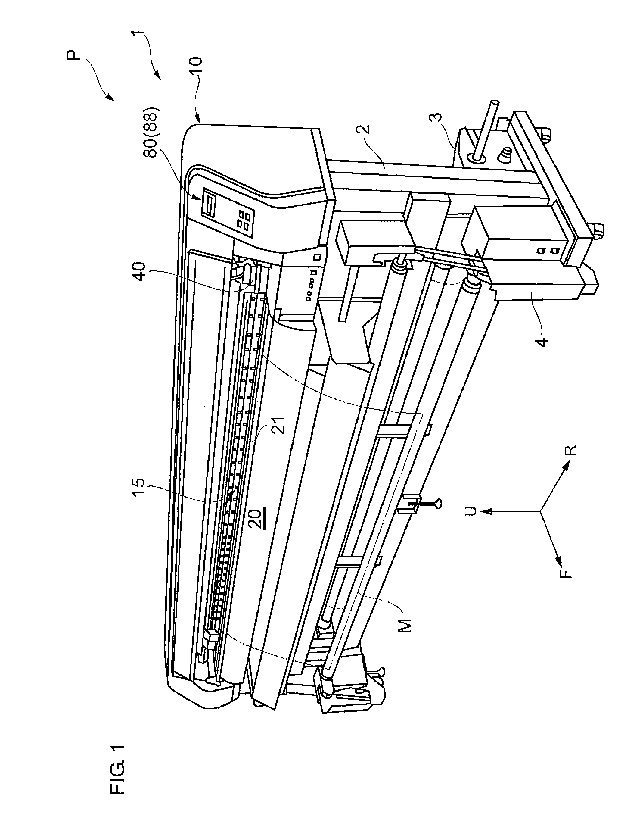
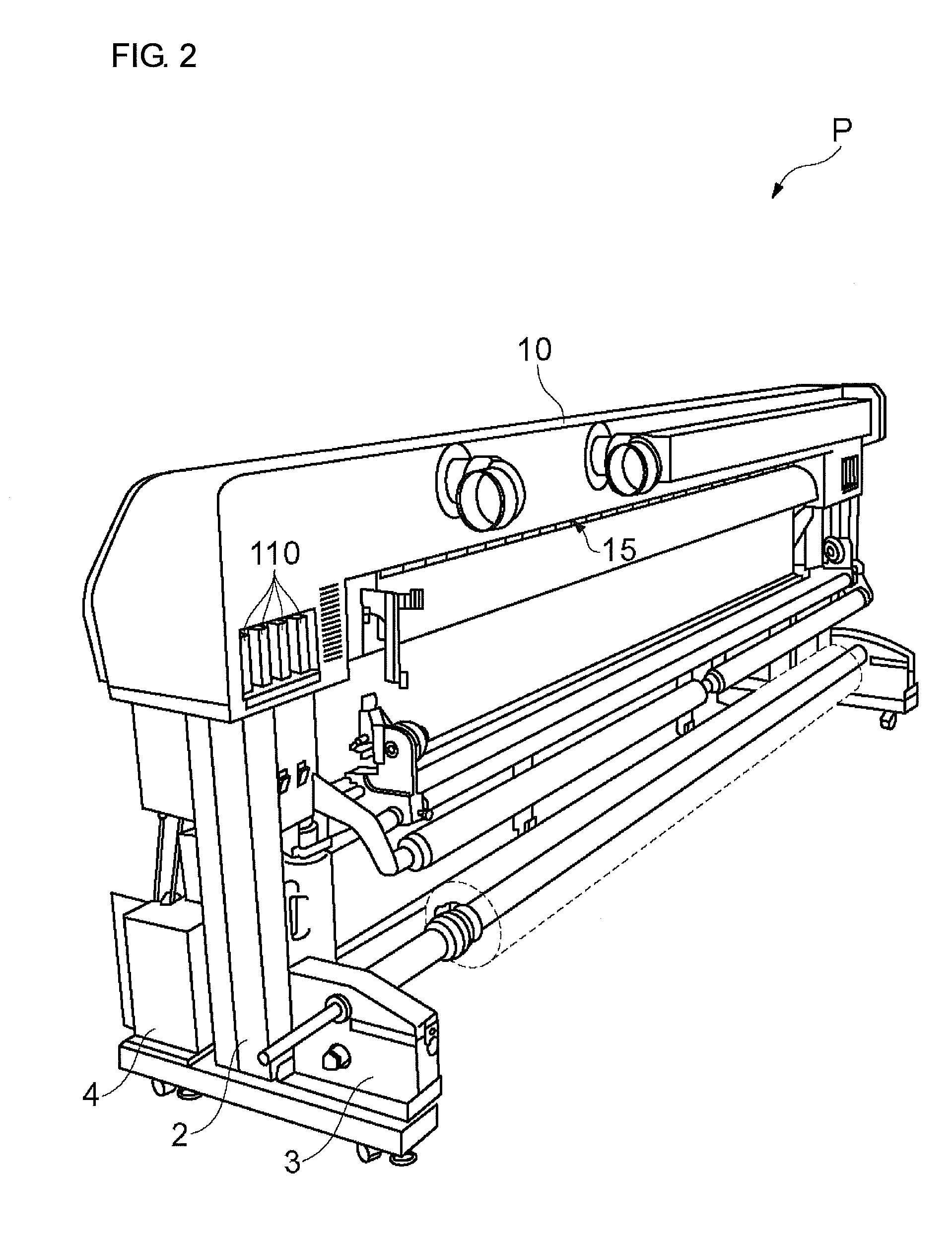
[0022]As an example of inkjet printers to which the present invention is applied, a structural example of an inkjet printer (hereinafter, referred to as “printer apparatus”) is employed in the following description. The structural example has orthogonal axes extending along a print surface of which one is used for moving a print medium and the other one is used for moving a print head and is of a UV curable type using an ultraviolet curable ink (so-called “UV ink) which is cured by an irradiation with ultraviolet light. FIG. 1 is a perspective view showing a printer apparatus P of this embodiment as seen diagonally from the front, FIG. 2 is a perspective view showing the same as seen diagonally from the back, and FIG. 3 shows main components of an apparatus body 1 of the printer apparatus P....


PUM


Abstract

An inkjet printer system includes a print head and a sub tank. The print head is configured to eject ink. The sub tank is provided above the print head and connected to the print head via a head-side supply passage. The sub tank has a first supplying hole and a second supplying hole which are connected to the head-side supply passage. A position of the first supplying hole is higher than a position of the second supplying hole.

Description

CROSS-REFERENCE TO RELATED APPLICATIONS[0001]This application claims priority under 35 U.S.C. §119 to Japanese Patent Application No. 2008-106919, filed Apr. 16, 2008. The contents of this application are incorporated herein by reference in their entirety.BACKGROUND OF THE INVENTION[0002]1. Field of the Invention[0003]The present invention relates to an inkjet printer system and an ink supply apparatus.[0004]2. Discussion of the Background[0005]An inkjet printer is an apparatus which forms images of information such as characters, graphics, patterns, and photographs on a print surface by ejecting fine particles of ink from a plurality of nozzles, which are formed in a print head, to deposit the ink on a print medium while moving the print head relative to the print medium. In the inkjet printer, since ink is consumed according to the ejection of the ink, a carriage of the print head or a printer body is provided with an ink tank (ink cartridge) having a volume based on the intended ...

Claims


Application Information

Patent Timeline
Patent Type & Authority Applications(United States)
IPC IPC(8): B41J2/195
CPCB41J2/175B41J2/17566B41J2/17509
Inventor TAMAKI, KAZUTAKA
Owner MIMAKI ENG
Why Eureka
Try Eureka