Outdoor lighting device

a technology for outdoor lighting and leds, which is applied in the direction of semiconductor devices, lighting and heating equipment with built-in power, and light sources with built-in hea

Inactive Publication Date: 2009-10-22
HON HAI PRECISION IND CO LTD
View PDF4 Cites 6 Cited by
  • Summary
  • Abstract
  • Description
  • Claims
  • Application Information

AI Technical Summary

Problems solved by technology

Outdoors, when a plurality of LEDs are used, powerin...

Method used


Image

  • Outdoor lighting device
  • Outdoor lighting device
  • Outdoor lighting device

Examples


first embodiment

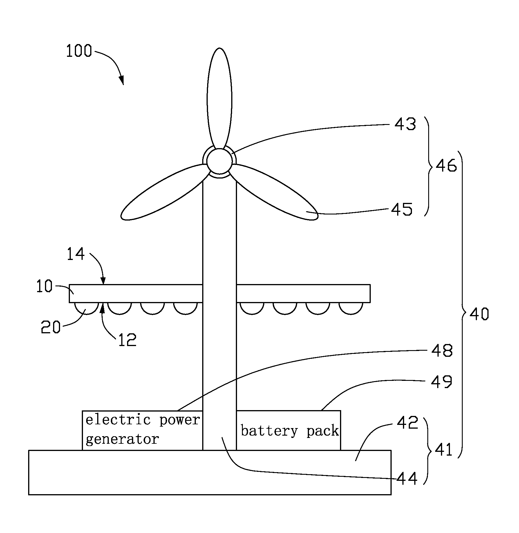
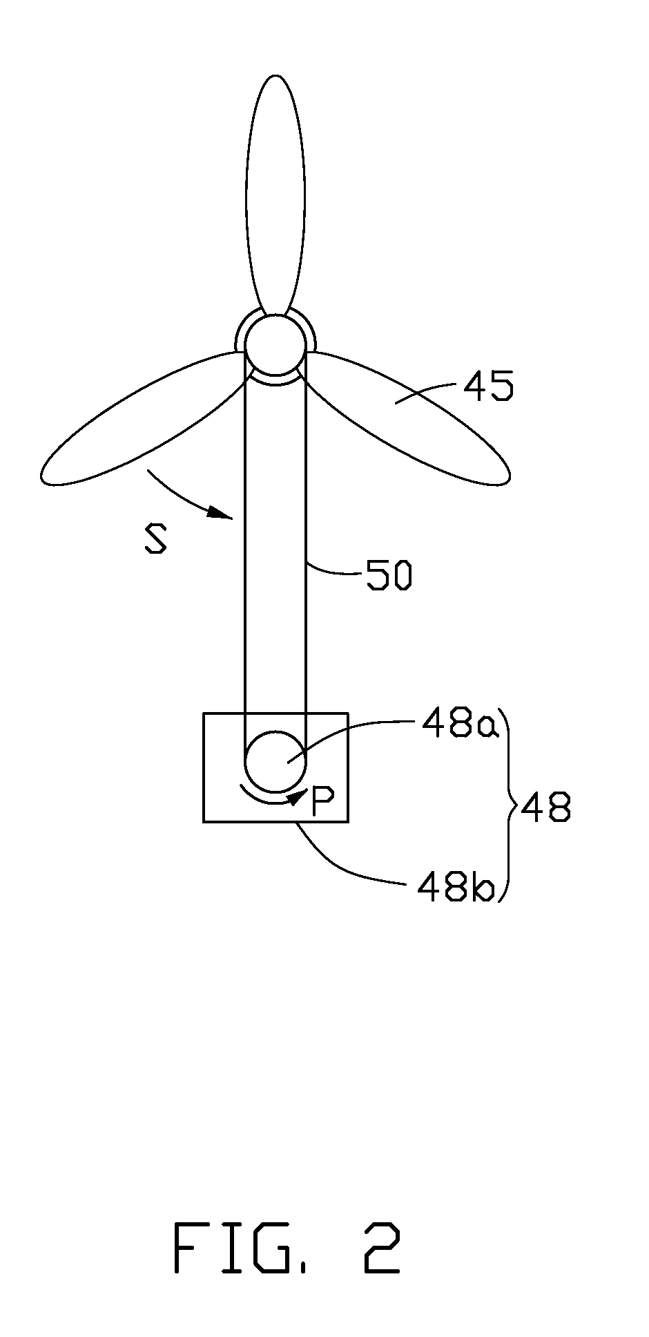
[0016]Referring to FIG. 1, an outdoor lighting device 100 in accordance with a first embodiment, is provided. The outdoor lighting device 100 includes a printed circuit board (PCB) 10, a plurality of light emitting diodes (LEDs) 20, and an electric power supply system 40.

[0017]The PCB 10 is metallic, and has a first surface 12 and an opposite second surface 14. The LEDs are mounted on the first surface 12, and are spaced apart from each other.

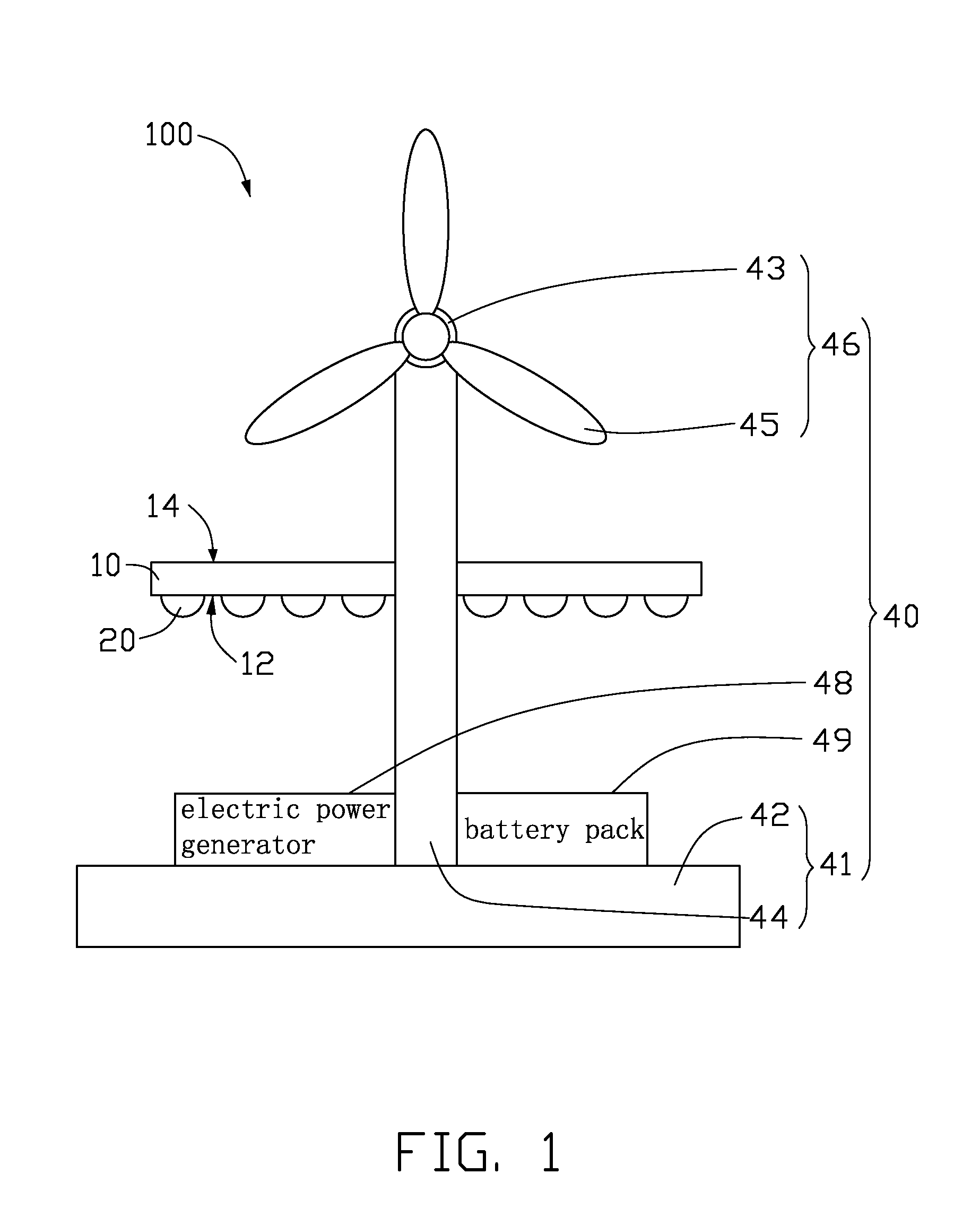
[0018]The electric power supply system 40 includes a supporter 41, an electric power generator 48, a battery pack 49, and an fan 46 having a shaft 43 and three blades 45 attached on the shaft 43. The supporter 41 includes a base 42 and an elongated post 44 attached on the base 42. The electric power generator 48 and the battery pack 49 are arranged on the base 42. The fan 46 is mounted on an end of the post 44. The printed circuit board 10 is also mounted on the post 44, between the fan 46 and the base 42.

[0019]Referring to FIG. 2, the electric...

second embodiment

[0022]Referring to FIG. 4, an outdoor lighting device 200 in accordance with a second embodiment, is provided. The outdoor lighting device 200 is essentially similar to the outdoor lighting device 100 illustrated above, however, a heat sink 60 is attached on the second surface 14 of the PCB 10. The heat sink 60 includes a heat conducting plate 62 and a plurality of fins 66 extending from the heat conducting plate 62. Configuration and cooperation of the blades 45 and the heat sink 60 can provide a compact efficient heat dissipating module.


PUM


Abstract

An outdoor lighting device includes a printed circuit board having a first surface and an opposite second surface; a plurality of light emitting diodes mounted on the first surface of the printed circuit board; and an electric power supply system. The electric power supply system includes a fan having a plurality of blades, and an electric power generator. The fan is arranged over the second surface of the printed circuit board. The electric power generator is mechanically connected to the fan and configured for converting rotation of the fan into electric power for the light emitting diodes. The blades dissipate heat generated by the light emitting diodes in rotation.

Description

BACKGROUND[0001]1. Technical Field[0002]The present invention relates to lighting devices, and particularly, to an outdoor lighting device with light emitting diodes.[0003]2. Description of Related Art[0004]Light emitting diodes (LEDs), which are solid state light emitting elements, are widely used in lighting.[0005]An LED is capable of producing a visible light in a certain wavelength, if an electric power is applied to the LED. However, 80% to 90% of the electrical energy is converted to heat, which needs to be dissipated, and only the small remainder is converted to the light.[0006]Outdoors, when a plurality of LEDs are used, powering the LEDs and heat dissipating for the LEDs are difficult.[0007]What is needed, therefore, is an outdoor lighting device, which overcomes the above problems.SUMMARY[0008]An outdoor lighting device includes a printed circuit board having a first surface and an opposite second surface; a plurality of light emitting diodes mounted on the first surface o...

Claims


Application Information

Patent Timeline
IPC IPC(8): F21L13/02
CPCF21S9/026F21S9/037F21S9/043F21V29/677F21Y2101/02Y02B20/72F21V29/004F21Y2115/10F21V29/773
Inventor CHEN, GA-LANE
Owner HON HAI PRECISION IND CO LTD
Why Eureka
Try Eureka