Image Display Apparatus, Image Display Control Method, and Computer Readable Medium Having an Image Display Control Program Recorded Therein

a technology of image display and control program, which is applied in the field of display of images, can solve the problems of deteriorating the visibility of images, vertebral disks, etc., and achieve the effect of reducing the visibility of the display target image due to the overlap of structure identification information thereon and deteriorating the visibility of the display target imag

Active Publication Date: 2009-10-22
FUJIFILM CORP
View PDF31 Cites 19 Cited by
  • Summary
  • Abstract
  • Description
  • Claims
  • Application Information

AI Technical Summary

Benefits of technology

[0034]The present invention displays a two dimensional display target image, in which the positions of each pixel are enabled to correspond to positions within an original image that represents a subject in two or more dimensions, based on the original image. Specification is received regarding which of the structure identifying information, each corresponding to an anatomical structure, is specified as display target structure identifying information to be displayed along with the display target image. The position of the anatomical structure, which is identified by the structure identifying information, within the display target image is specified, based on the structure information, in which structure identifying information that identifies each of a plurality of predetermined anatomical structures within the subject and structure position information that represents the positions of the anatomical structures within the original image are correlated, and the correspondenc

Problems solved by technology

However, a great number of pieces of identifying information are displayed within diagnostic images, which deteriorates t

Method used


Image

  • Image Display Apparatus, Image Display Control Method, and Computer Readable Medium Having an Image Display Control Program Recorded Therein
  • Image Display Apparatus, Image Display Control Method, and Computer Readable Medium Having an Image Display Control Program Recorded Therein
  • Image Display Apparatus, Image Display Control Method, and Computer Readable Medium Having an Image Display Control Program Recorded Therein

Examples


Embodiment Construction

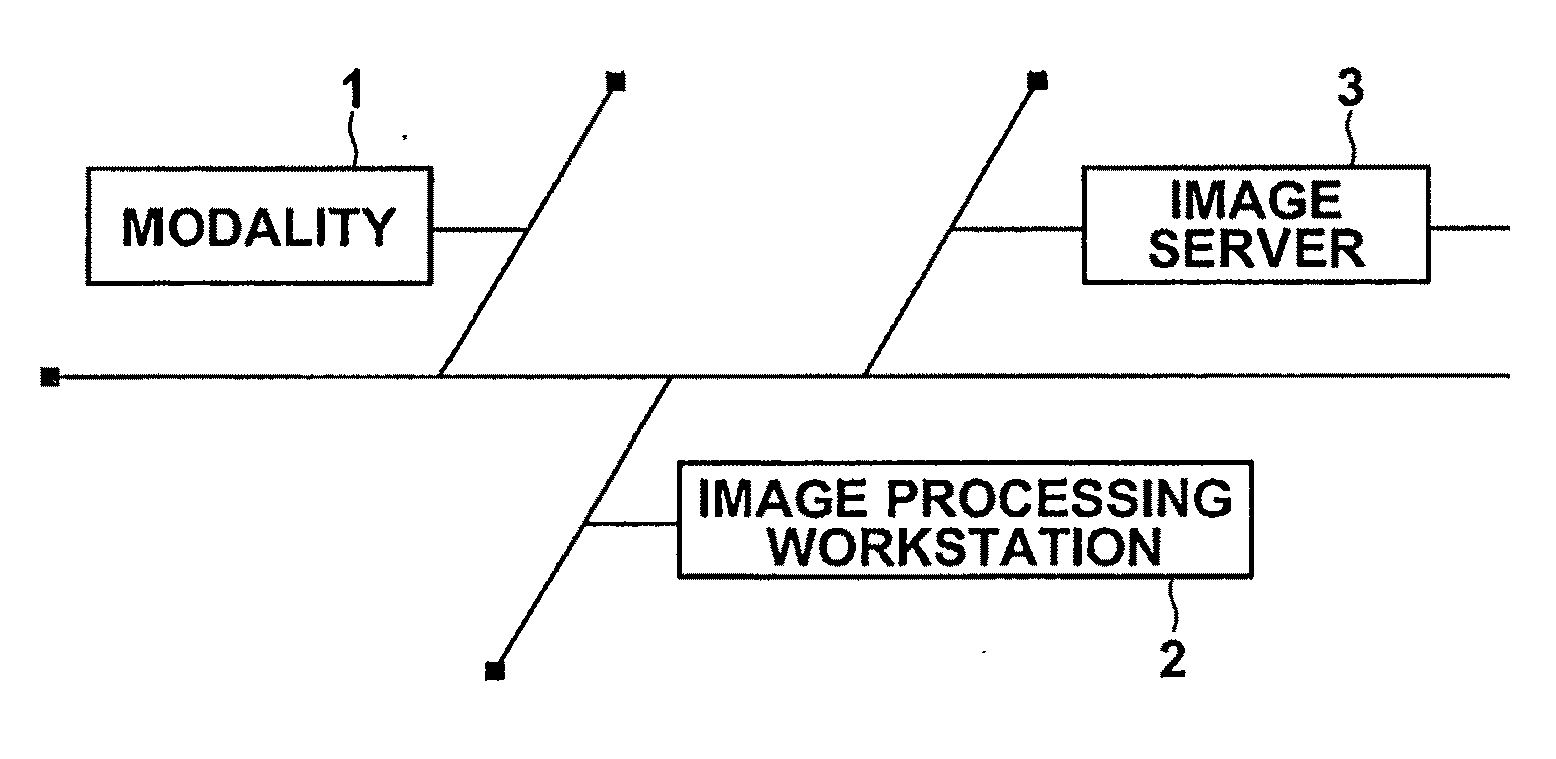
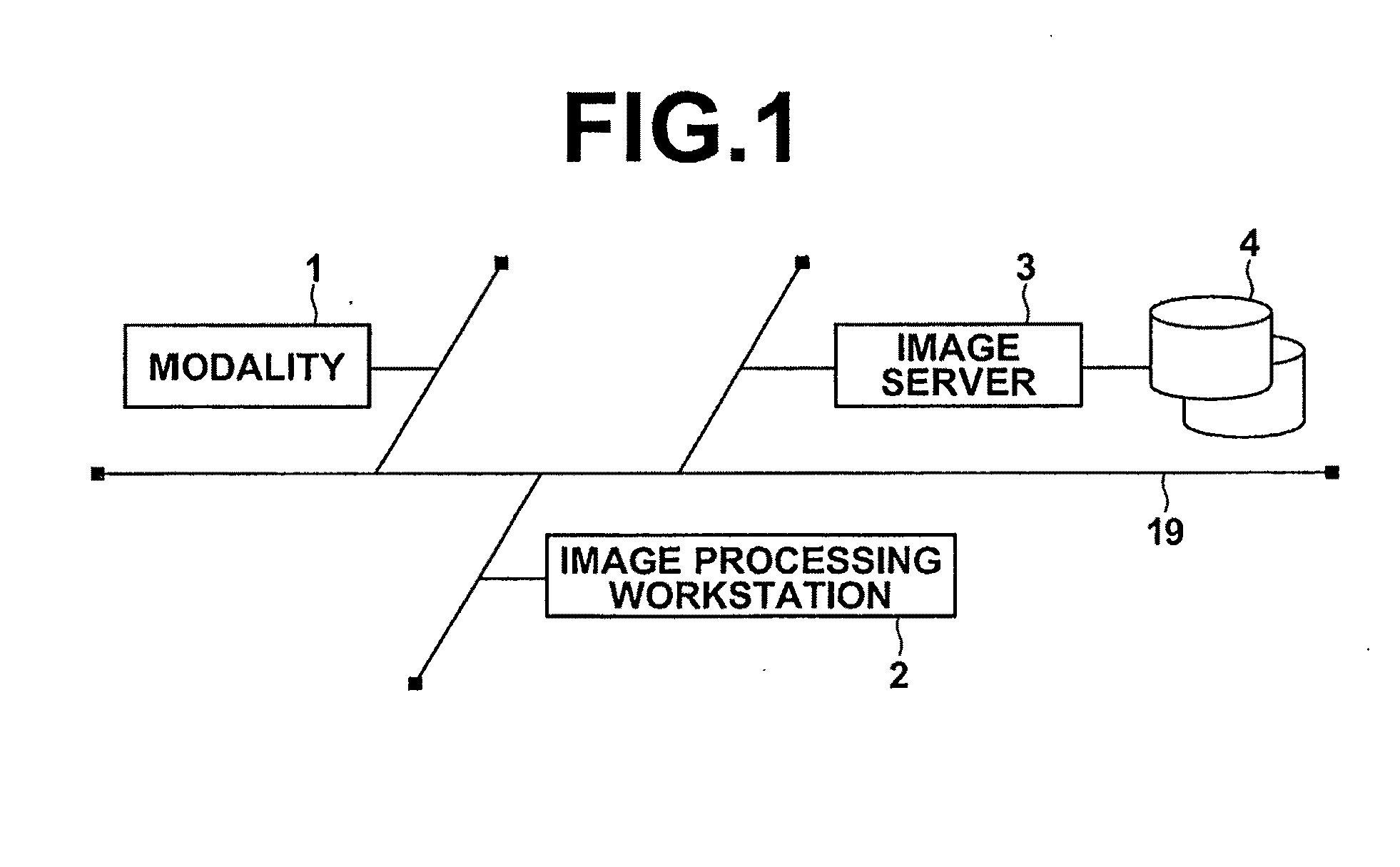
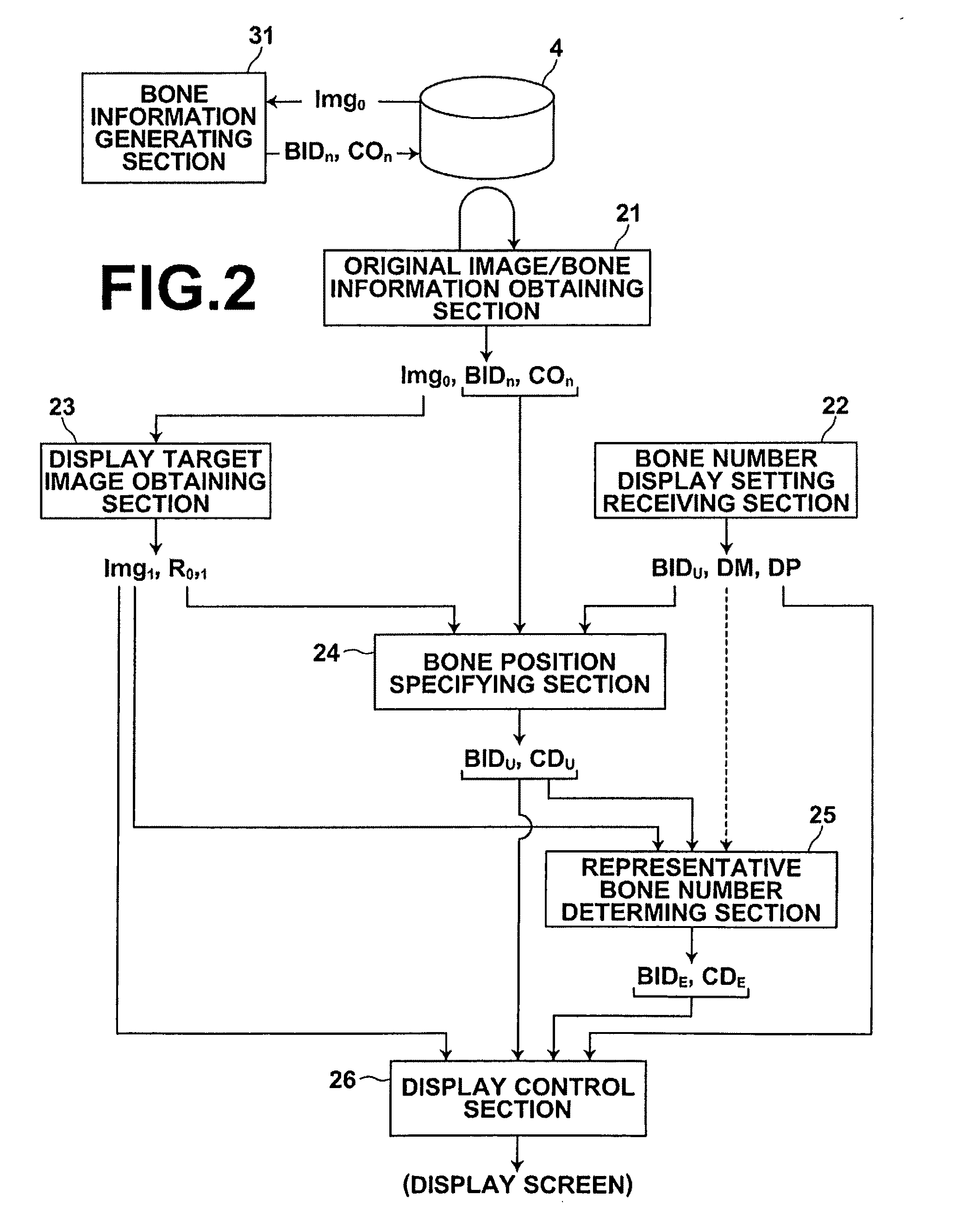
[0057]Hereinafter, a process in which identifying information that identifies vertebral bones and ribs are displayed along with a display target axial tomographic image that constitutes a portion of a three dimensional original image obtained by CT or MRI will be described as an embodiment of the present invention, with reference to the attached drawings. Note that in the following description, the identifying information will be referred to as vertebral bone numbers and rib numbers. In cases that it is not particularly necessary to clearly distinguish between the two, they will simply be referred to as bone numbers. In the following description, the vertebral bone numbers will be referred to as first through seventh cervical vertebrae, first through twelfth thoracic vertebrae, first though fifth lumbar vertebrae. The ribs numbers will be referred to as first through twelfth left ribs, and first through twelfth right ribs. Alternatively, symbols such as C1 through C7, T1 through T12...


PUM


Abstract

Specification is received regarding which structure identifying information, each corresponding to an anatomical structure, is specified as display target structure identifying information to be displayed with a display target image when displaying the display target image, in which the positions of each pixel correspond to positions within an original image. The position of the anatomical structure identified by the structure identifying information is specified, based on structure information, in which structure identifying information that identifies anatomical structures and structure position information that represents the positions of the anatomical structures within the original image are correlated, and the correspondence of positions between the original image and the display target image. The display target structure identifying information is displayed with the display target image such that a user can recognize that the anatomical structure identified by the display target structure identifying information is displayed at the specified position.

Description

BACKGROUND OF THE INVENTION[0001]1. Field of the Invention[0002]The present invention is related to a technique for displaying images of subjects that include predetermined anatomical structures, along with information that identifies the anatomical structures.[0003]2. Description of the Related Art[0004]There is a known technique for administering image analysis on diagnostic images obtained by MRI imaging that include spinal columns of humans (as disclosed in K. L. Weiss et al., “Automated Spine Survey Iterative Scan Technique”, Radiology, Vol. 239, No. 1, pp. 255-262, The Radiological Society of North America, 2006). In this technique, image analysis is administered to extract vertebral disks within the image. Then, symbols for identifying the vertebra (C1 through C7 for the first through seventh cervical vertebrae, T1 through T12 for the first through twelfth thoracic vertebrae, and L1 through L5 for the fifth through fifth lumbar vertebrae) are attached with respect to each of ...

Claims


Application Information

Patent Timeline
IPC IPC(8): G06K9/00G16H30/40
CPCG06F19/321G06F19/3487G06T7/0089G06T2207/30012G06T2207/10081G06T2207/10088G06T2207/20128G06T19/00G06T7/149G16H15/00G16H30/40
Inventor WANG, CAIHUAMORIYA, YOSHIYUKI
Owner FUJIFILM CORP
Why Eureka
Try Eureka