Display apparatus

a display device and display technology, applied in the field of display devices, can solve the problems of lowering the visibility of the screen, the problem of moire fringes being observed on the screen, and the display could actually become more difficult to view

Inactive Publication Date: 2003-03-13
DAI NIPPON PRINTING CO LTD
View PDF6 Cites 41 Cited by
  • Summary
  • Abstract
  • Description
  • Claims
  • Application Information

AI Technical Summary

Problems solved by technology

In a display device, and particularly in a liquid-crystal display device, the contrast at the viewing line of an observer thereof is lowered at an inclination from the normal direction to the screen, in comparison with the contrast at the normal direction, leading to problems such as a lowering of the visibility of the screen.
When using a lenticular lens as a microlens array in display having a matrix formed on the surface thereof, such as a liquid-crystal display (LCD), a plasma display panel (PDP), an electroluminescent display (ELD), or a field emission display (FED) or the like, depending upon the positional relationship b

Method used


Image

  • Display apparatus
  • Display apparatus
  • Display apparatus

Examples


second embodiment

[0052] the present invention is described in detail below, with reference to the drawings.

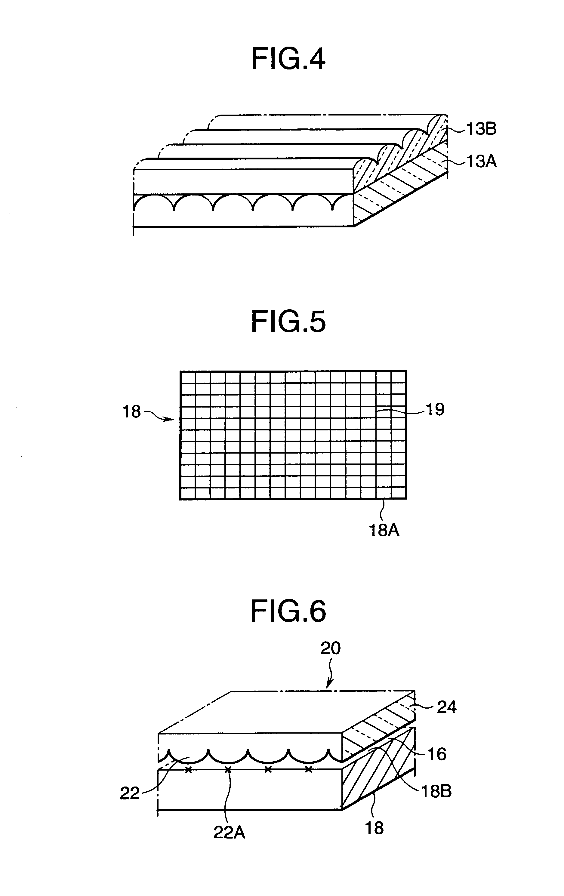
[0053] The display apparatus 20 of the second embodiment, as shown in FIG. 6, has a lens sheet 24 having a plurality of unit columnar lenses 22 provided on the observation side of the display panel 18, with an intervening air layer 16, the position of the focal point of the unit columnar lenses 22 substantially coinciding with the display surface 18B of the display panel 18.

third embodiment

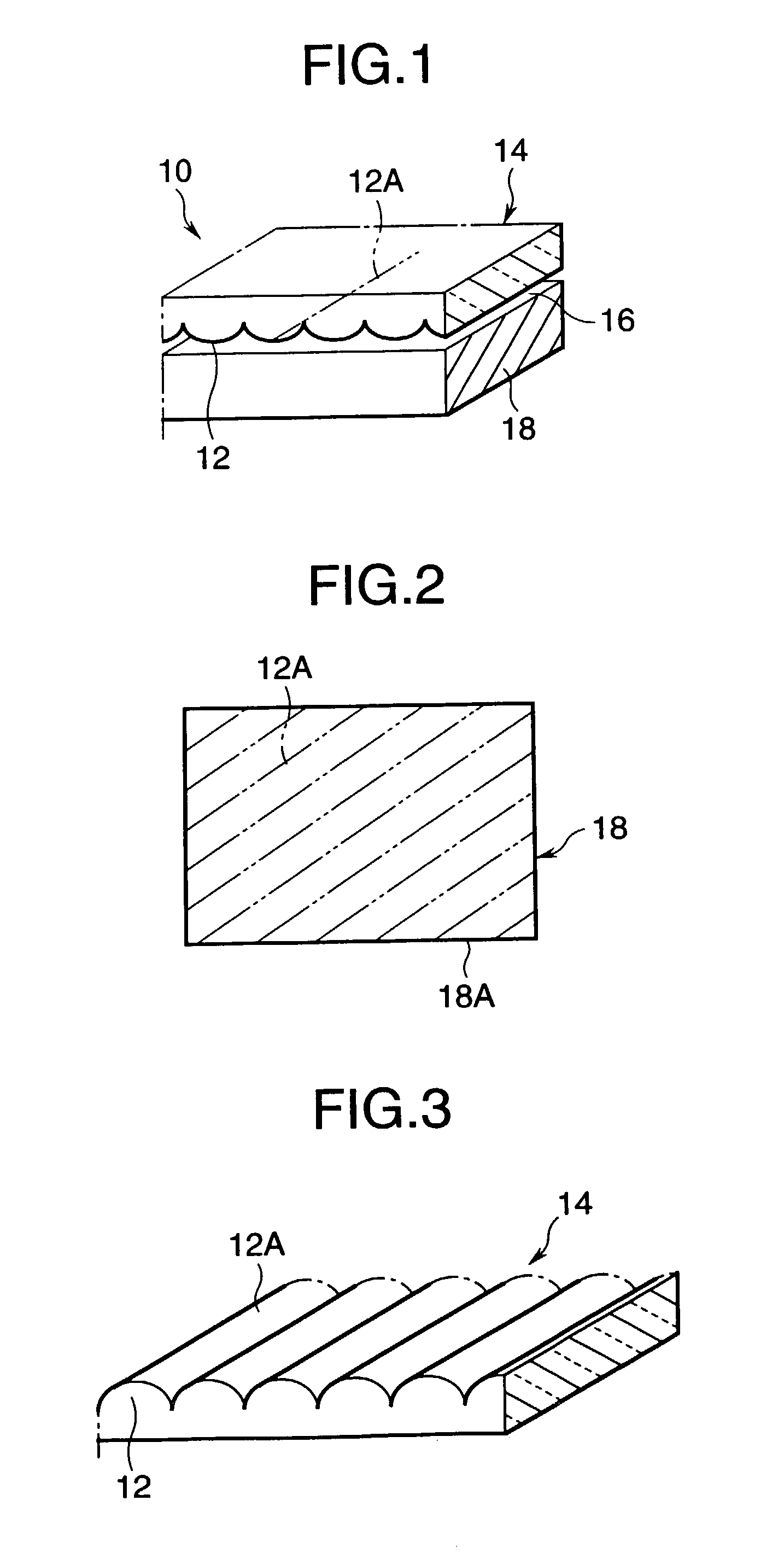
[0054] Because the material and method of manufacturer of the lens sheet 24 are the same as described above with regard to the above example, they will be omitted herein. While the lens sheet 24, similar to the lens sheet 14 shown in FIG. 3, has a plurality of unit columnar lenses having semicircular cross-sectional shapes, and arranged so as to be parallel to one another, it is also possible, as shown as the lens sheet 26 of a display apparatus 21 shown in FIGS. 7 and 8, to arrange a plurality of unit lenses 28 having semicircular cross-sectional shapes in two dimensions. In FIG. 7, the reference numeral denotes the focal point 28A of the unit lens 28. The shape of the unit lens 28 is not limited to that indicated above, and can also be a cross-sectional shape that is a sine curve, a concave-lens shape, or a semielliptical shape, as long as the axis lines thereof are arranged next to one another so as to be mutually parallel in one direction.

[0055] From the standpoint of suppressi...

first embodiment

[0107] The second example of the display apparatus, with the exception that the ridge lines of the lens sheet and the edges of the display panel make an angle of 85.degree., is the same as the

[0108] The third example of the display apparatus, with the exception of using the lens sheet C, is the same as the first embodiment.

[0109] The fourth example of the display apparatus, with the exception of using the lens sheet D, is the same as the first example.

[0110] The first comparison example, with the exception that the ridge lines of the lens sheet and the edges of the display panel make an angle of 0.degree., is the same as the first example.

[0111] The second comparison example, with the exception that the ridge lines of the lens sheet and the edges of the display panel make an angle of 90.degree., is the same as the first example.

[0112] The third comparison example, with the exception of using the lens sheet B, is the same as the first example.

[0113] The fourth comparison example, wit...


PUM


Abstract

A display apparatus has a lens sheet with a plurality of unit columnar lenses arranged so as to be parallel to one another, and is disposed on the observation side of a display panel, spaced therefrom by a layer of air. The direction of the ridge lines of the unit columnar lenses of the lens sheet, seen from the observation side, are non-parallel to the direction of an edge of the display panel.

Description

[0001] 1. Field of the Invention[0002] The present invention relates to a display apparatus using a lens sheet that, by the refraction action of a unit columnar lens or a unit lens, provides increased widening of light from a display panel. 2. Description of the Related Art[0003] In a display device, and particularly in a liquid-crystal display device, the contrast at the viewing line of an observer thereof is lowered at an inclination from the normal direction to the screen, in comparison with the contrast at the normal direction, leading to problems such as a lowering of the visibility of the screen.[0004] In recent years, with an increase in the screen size of liquid-crystal displays, there has been a desire to improve the visibility of the screen when it is viewed at an inclination. Based on this desire, and as disclosed, for example, in Japanese Unexamined Patent Applicaton publicaton H5-249453, there has been proposed the use of a microlens array on the observed side of a liqu...

Claims


Application Information

Patent Timeline
IPC IPC(8): G09F9/00G02F1/1335G03B21/62
CPCG03B21/625
Inventor ODA, KUMPEIARAKAWA, HUMIHIROKASHIMA, KEIJI
Owner DAI NIPPON PRINTING CO LTD
Why Eureka
Try Eureka