Mechanism for maintaining a desired temperature in a truck cab including an auxiliary motor for operating a vehicle air conditioning pump as well as a secondary generator for providing either power when the vehicle is parked or a convective heat transfer via a fluid jacket communicating with a vehicle mounted convective heat transfer network

a technology of convective heat transfer and auxiliary motors, which is applied in the direction of positive displacement liquid engines, pumping, lighting and heating apparatus, etc., can solve the problem of restricting the consumption power of a

Inactive Publication Date: 2009-10-29
HAMILTON DAVID
View PDF27 Cites 12 Cited by
  • Summary
  • Abstract
  • Description
  • Claims
  • Application Information

AI Technical Summary

Benefits of technology

[0008]The present invention discloses a number of alternative assemblies for providing either air conditioning or heat to a truck cab interior and which utilizes an auxiliary power source additional to the main engine (such as diesel). Variants include the provision of a secondary AC, DC or hydraulic motor for operating an AC pump which also connected to the main engine. Related variants include providing a secondary generator for providing auxiliary power

Problems solved by technology

Further, and upon a rotational speed of the engine being lower than a predetermined speed or when a power generation efficiency due to the engine i

Method used


Image

  • Mechanism for maintaining a desired temperature in a truck cab including an auxiliary motor for operating a vehicle air conditioning pump as well as a secondary generator for providing either power when the vehicle is parked or a convective heat transfer via a fluid jacket communicating with a vehicle mounted convective heat transfer network
  • Mechanism for maintaining a desired temperature in a truck cab including an auxiliary motor for operating a vehicle air conditioning pump as well as a secondary generator for providing either power when the vehicle is parked or a convective heat transfer via a fluid jacket communicating with a vehicle mounted convective heat transfer network
  • Mechanism for maintaining a desired temperature in a truck cab including an auxiliary motor for operating a vehicle air conditioning pump as well as a secondary generator for providing either power when the vehicle is parked or a convective heat transfer via a fluid jacket communicating with a vehicle mounted convective heat transfer network

Examples


Embodiment Construction

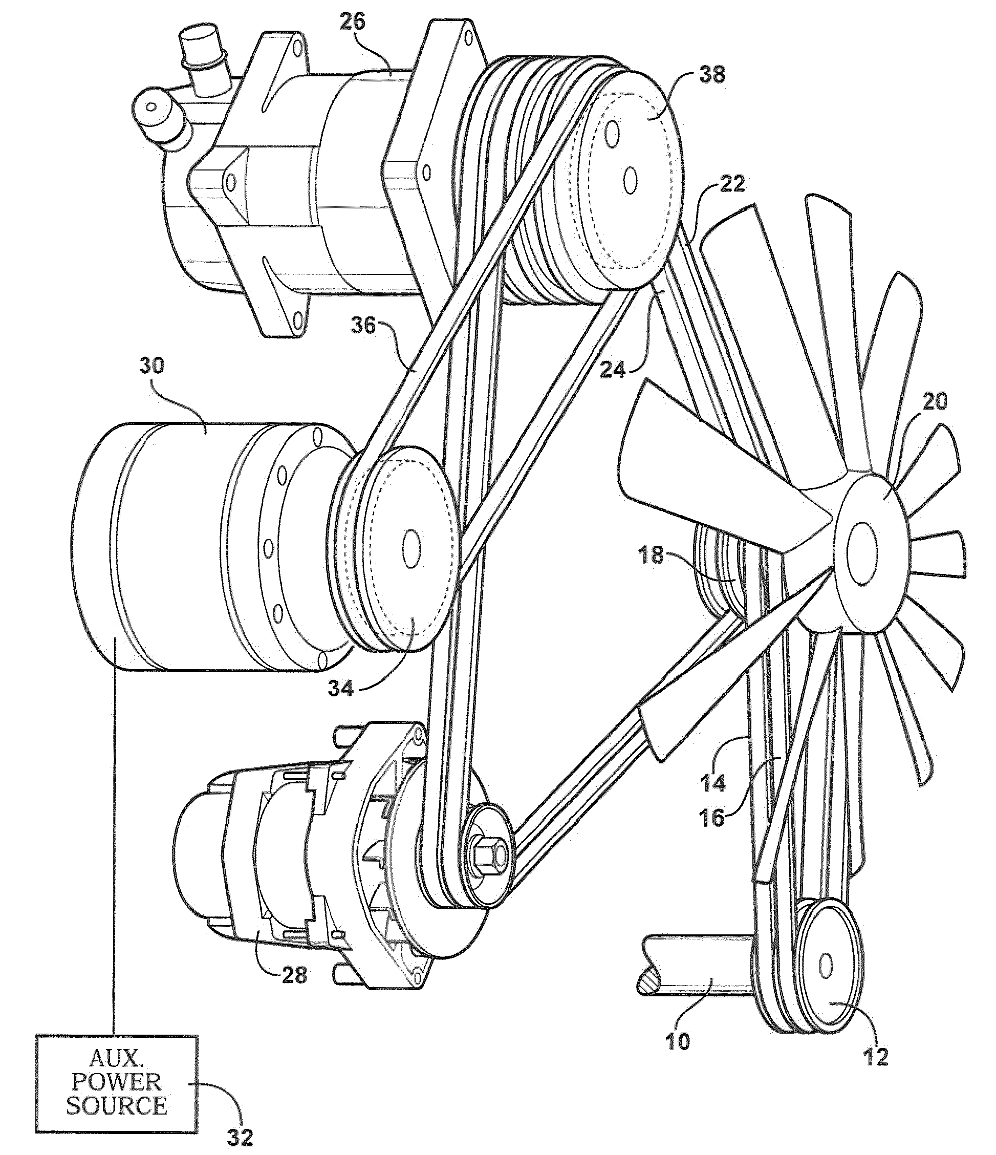
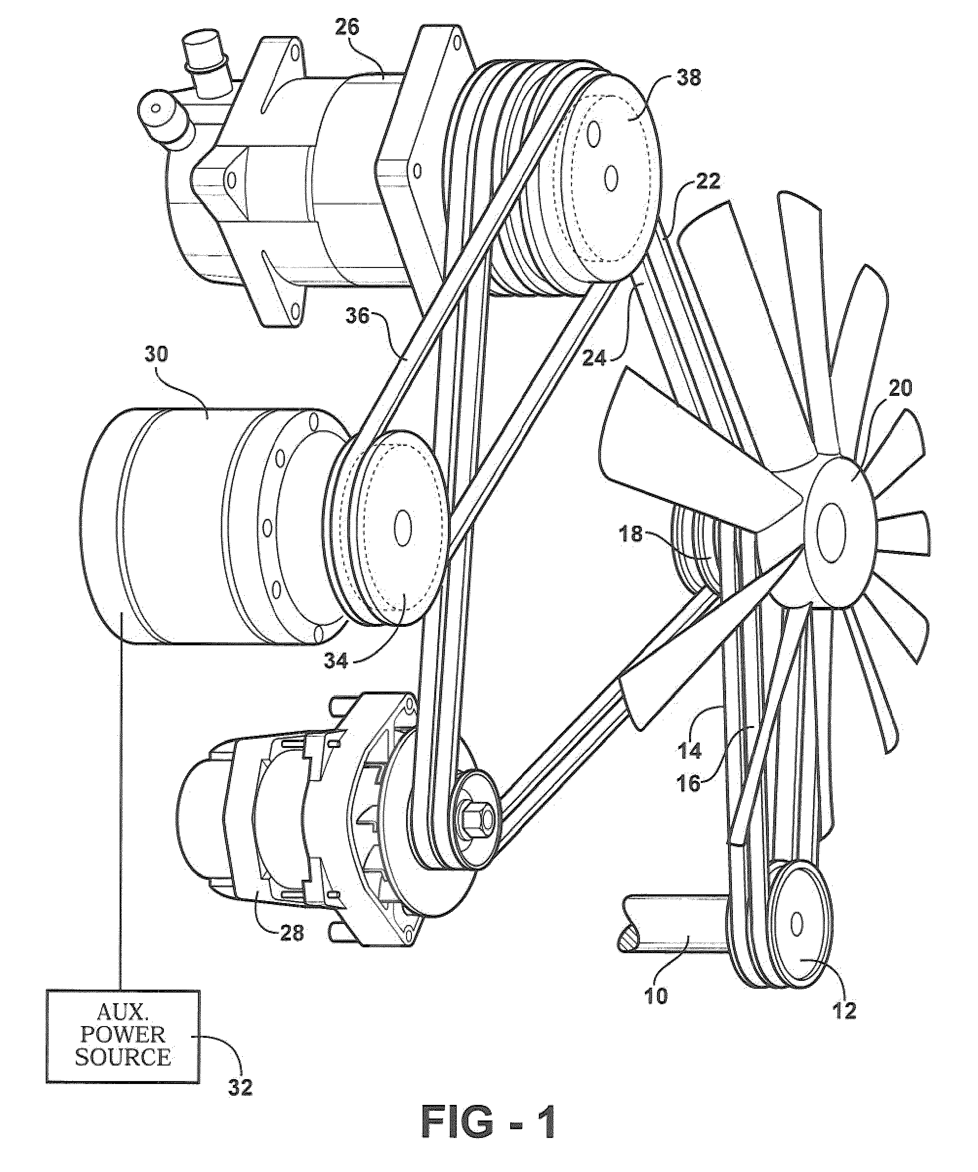
[0020]Referring now to FIG. 1 a general illustration is shown of a first variant and which includes an air conditioning pump which is operable when the main diesel engine is inactive. A main engine (not shown but which includes such as a diesel motor) drives a shaft 10 to which is attached a double belted wheel 12. Associated belts 14 and 16 extend from the wheel 12 and received at opposite ends within like seating locations of a rotating hub 18 associated with a multi-bladed fan 20.

[0021]In a primary operating arrangement, the driving rotation of the hub 18 (via the main motor output shaft 10) is transferred via a pair of belts 22 and 24 supported in a generally triangular shaped and supporting fashion about both an air conditioning pump 26 and a separate battery charging alternator 28. In this arrangement, an output force of the main motor (not shown) is transferred via the belts 22 and 24 to the AC pump 26, while at the same time recharging the batteries through the alternator 28...


PUM


Abstract

An assembly for providing either of auxiliary power and/or convective heating of an auxiliary exhaust, such as provided via a water jacket surrounding the engine exhaust interposed between an auxiliary generator and the truck tail pipe and circulated by a pump to provide heat to the cab interior. A further alternate variant provides for solar panels mounted to an exterior cab location and for operating the vehicle electric motor with or without the need for batteries. An associated articulating or pivoting mechanism is provided for displacing the solar panels from a first position in which it is stored against a rear surface of the cab, and to a second position in which is it arrayed upwardly above the cab.

Description

CROSS REFERENCE TO RELATED APPLICATIONS[0001]The present application is a continuation-in-part of U.S. application Ser. No. 11 / 985,090, filed Nov. 14, 2007, and entitled Diesel Track Battery Disclosure.FIELD OF THE INVENTION[0002]The present invention discloses a number of alternative assemblies for providing either air conditioning or heat to a truck cab interior and which utilizes an auxiliary power source additional to the main engine (such as diesel). Variants include the provision of a secondary AC, DC or hydraulic motor for operating an AC pump also connected to the main engine. Related variants include providing a secondary generator for providing auxiliary power to the vehicle AC as well as providing additional heat through a secondary water jacket associated with the generator and which operates in cooperation with a similar convective fluid network associated with the main motor. Yet additional variants include the provision of elevatable solar panels secured to the vehicl...

Claims


Application Information

Patent Timeline
IPC IPC(8): B60H1/32F04B17/00F25B27/00
CPCB60H1/3222
Inventor HAMILTON, DAVID
Owner HAMILTON DAVID
Why Eureka
Try Eureka