Electric compressor

Inactive Publication Date: 2009-10-29
SANDEN CORP
View PDF4 Cites 1 Cited by
  • Summary
  • Abstract
  • Description
  • Claims
  • Application Information

AI Technical Summary

Benefits of technology

[0010]Thus, in the electric compressor according to the present invention, because injection of resin into the housing and the time for curing the injected resin are not necessary as compared with the conventional structure, the assembling efficiency is very high. Further, because resin injection is not necessary, it becomes possible to reuse the sealed terminal.

Problems solved by technology

However, in such an electric compressor in which the connection section between the electroconductive pin of the sealed terminal and the socket is secured with the insulative resin injected into the housing, there occurs a waiting time for curing the insulative resin injected into the housing, and there are a problem that the assembling efficiency for the compressor is reduced, a problem that the sealed terminal is secured with the resin and cannot be reused, etc.

Method used


Image

  • Electric compressor
  • Electric compressor

Examples


Embodiment Construction

[0013]Hereinafter, a desirable embodiment of the present invention will be explained referring to figures.

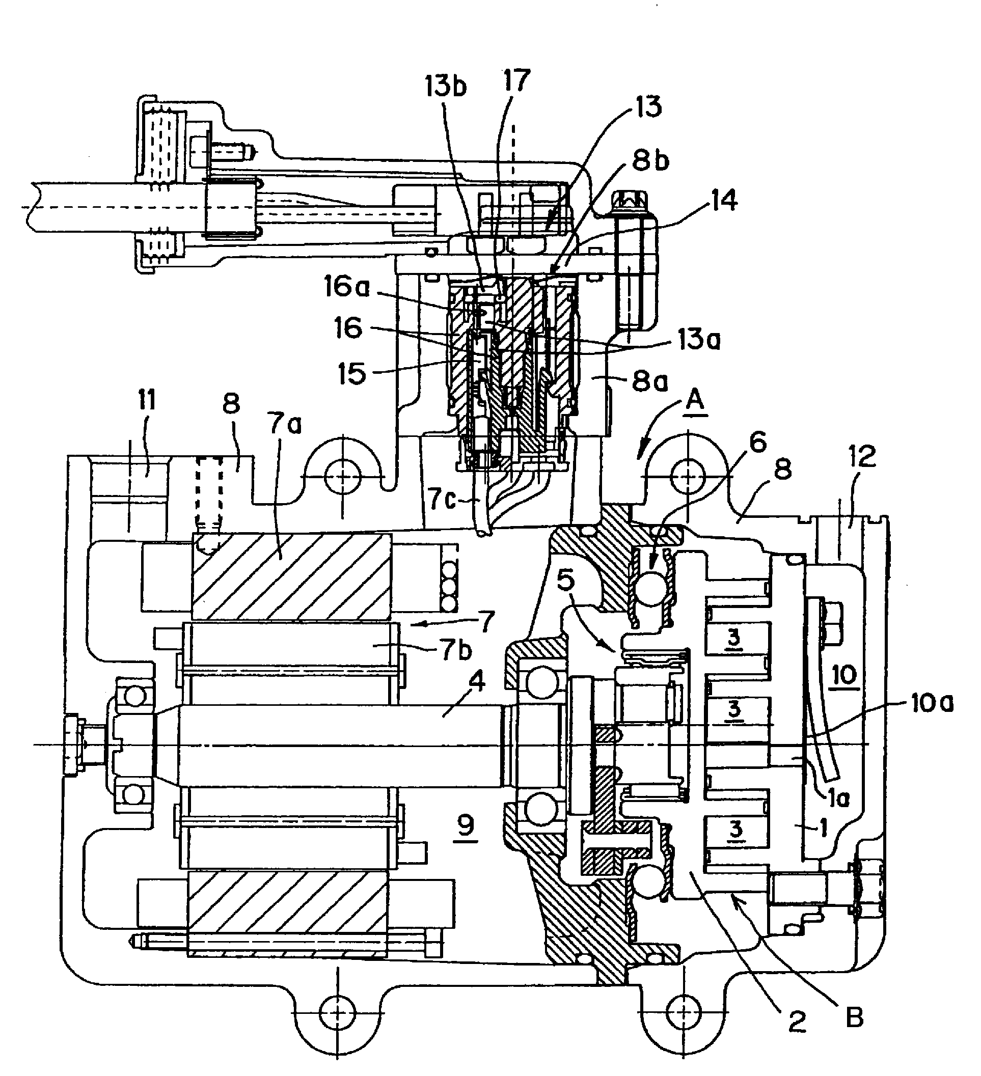
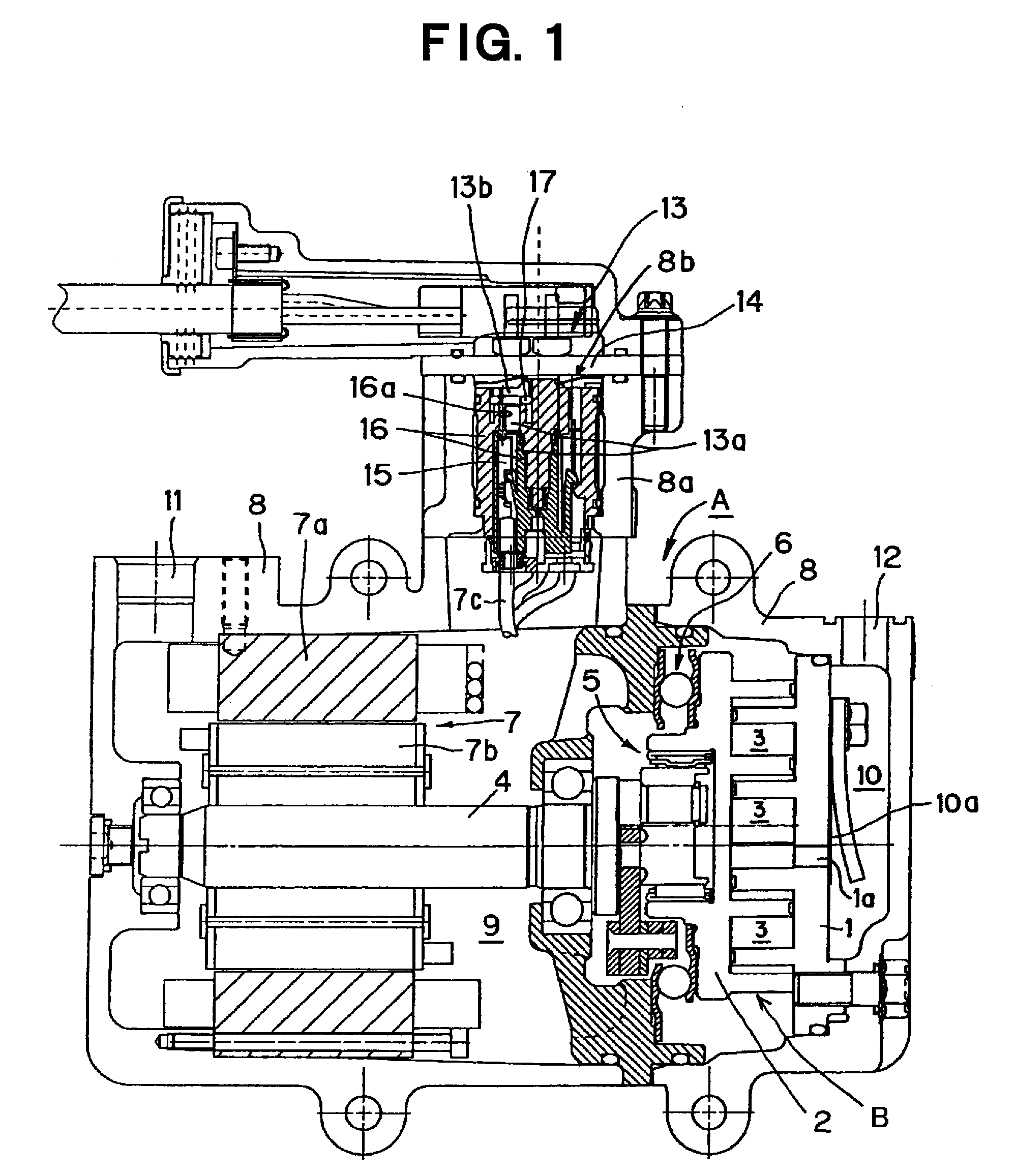
[0014]FIG. 1 depicts an electric compressor according to an embodiment of the present invention, and in this embodiment, it is structured as a scroll-type electric compressor A. Scroll type compressor A has a fixed scroll 1 comprising an end plate formed with a discharge hole la in its center and a spiral body, and a movable scroll 2 comprising an end plate and a spiral body. The spiral body of fixed scroll 1 and the spiral body of movable scroll 2 engage with each other, and form a plurality of pairs of operational spaces 3. A main shaft 4, a movement transforming mechanism 5 for transforming the rotational movement of main shaft 4 to an orbital movement and transmitting the orbital movement to movable scroll 2, and a rotation preventing mechanism 6 for preventing the rotation of movable scroll 2 are disposed in the compressor. A compression mechanism B is formed by these fixed...


PUM


Abstract

An electric compressor having a compression mechanism, an electric motor for driving the compression mechanism, and a housing for containing the compression mechanism and the electric motor. An opening formed in the housing is closed with a lid member to which a sealed terminal is attached, and an electroconductive pin of the sealed terminal is fitted into a socket connected to a lead wire of the electric motor. The socket is embedded in an insulative member, and the electroconductive pin of the sealed terminal is inserted into a hole formed in the insulative member and is fitted into the socket. An insulation section that surrounds the base portion of the electroconductive pin and the insulative member hold a ring member that is formed from an insulative elastic material and surrounds the electroconductive pin, and this portion held is sealed and insulated by elastic deformation of the ring member. Injection and curing of resin for insulation, which have been carried out for a conventional structure, are not necessary, so that the electric compressor has high assembling efficiency and whose sealed terminal can be reused.

Description

TECHNICAL FIELD OF THE INVENTION[0001]The present invention relates to an electric compressor, and specifically, to improvement of an insulation structure of an electric connection section for supplying electric power to an electric motor.BACKGROUND ART OF THE INVENTION[0002]An electric compressor is disclosed in Patent document 1, etc., which has a compression mechanism, an electric motor for driving the compression mechanism and a housing for containing the compression mechanism and the electric motor and wherein an opening formed in the housing is closed with a lid member to which a sealed terminal is attached, and an electroconductive pin of the sealed terminal is fitted into a socket connected to an end section of a lead wire of the electric motor. In the electric compressor disclosed in Patent document 1, etc., in order to insulate the connection section between the electroconductive pin and the socket, generally, after both parts are connected, an insulative resin is injected...

Claims


Application Information

Patent Timeline
IPC IPC(8): H01R13/52
CPCF04B35/04F04B39/12F04C18/0215H02K7/14H01R13/521H02K5/12H02K5/225F04C2240/803
Inventor NEGISHI, YASUTAKAMATSUSHIMA, MASAHIRO
Owner SANDEN CORP
Why Eureka
Try Eureka