Backlight System and Liquid Crystal Devices with the Same

Inactive Publication Date: 2014-03-06
TCL CHINA STAR OPTOELECTRONICS TECH CO LTD
View PDF3 Cites 0 Cited by
  • Summary
  • Abstract
  • Description
  • Claims
  • Application Information

AI Technical Summary

Benefits of technology

The invention introduces a backlight system and liquid crystal device that have high assembly efficiency, low labor cost, and low risk of scratching the liquid crystal panels during the assembling process of the backlight system. The backlight system includes a back plate, optical films, and a protecting member. The back plate has at least two main connecting members, and the front ends and rear ends of the main connecting members are connected to form the back plate. The optical films are embedded in a space between the top plate and the down plate. The protecting member is fixed on the top plate and includes a first portion arranged above the top plate to separate the top plate and the liquid crystal panel above the top plate, and a second portion arranged on a down surface of the top plate to separate the top plate and the optical films so as to protect the liquid crystal panel and the optical films.

Problems solved by technology

It is obvious that a lot of manual processes and assembling time are needed to complete the above assembly processes of liquid crystal display module.
Also, the back plates with larger size are difficult to be transported.
While the back plates are generally made by metallic materials with low thermal insulation, the above-mentioned side of the back plate thus may have light leakage problem due to the high temperature.

Method used


Image

  • Backlight System and Liquid Crystal Devices with the Same
  • Backlight System and Liquid Crystal Devices with the Same
  • Backlight System and Liquid Crystal Devices with the Same

Examples


Embodiment Construction

[0032]Embodiments of the invention will now be described more fully hereinafter with reference to the accompanying drawings, in which embodiments of the invention are shown.

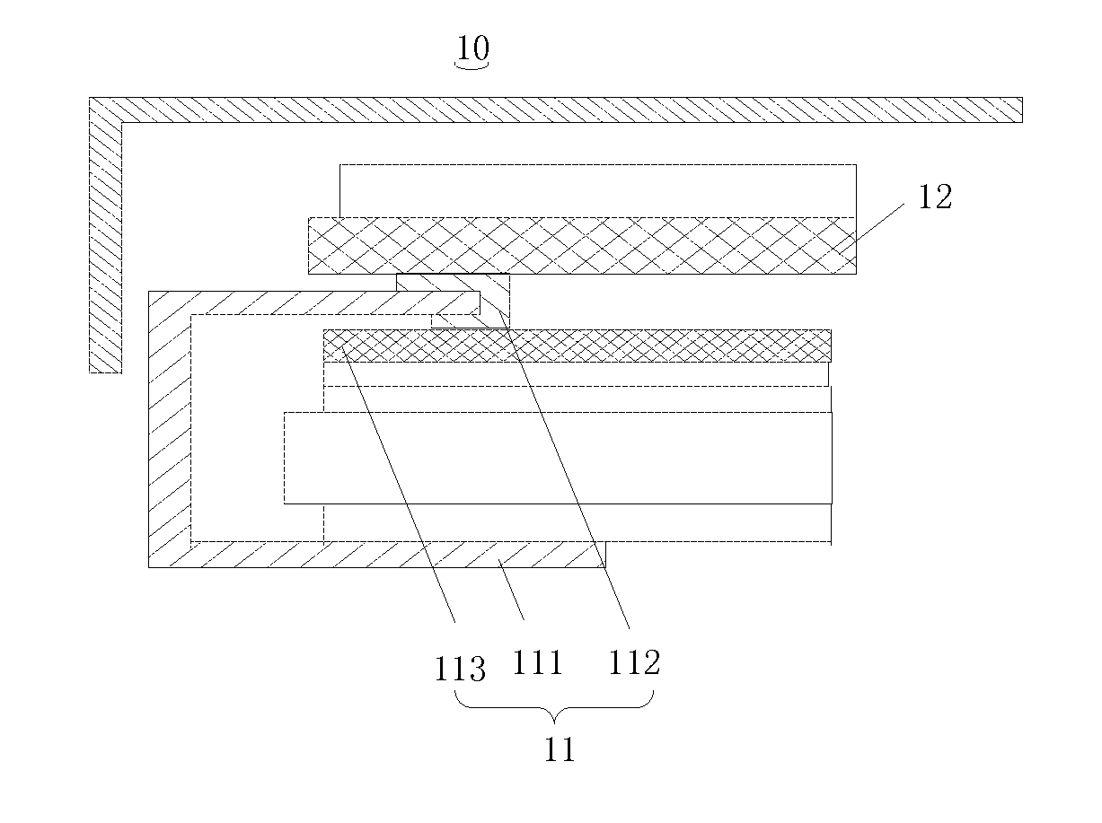
[0033]FIG. 1 is a partial sectional view of the backlight system of one embodiment. As shown, a backlight system 11 of a liquid display device 10 includes a back plate 111, a protecting member 112, and an optical film 113. The back plate 111 includes at least two main connecting members, and front ends and rear ends of the main connecting members are connected to form the back plate 111.

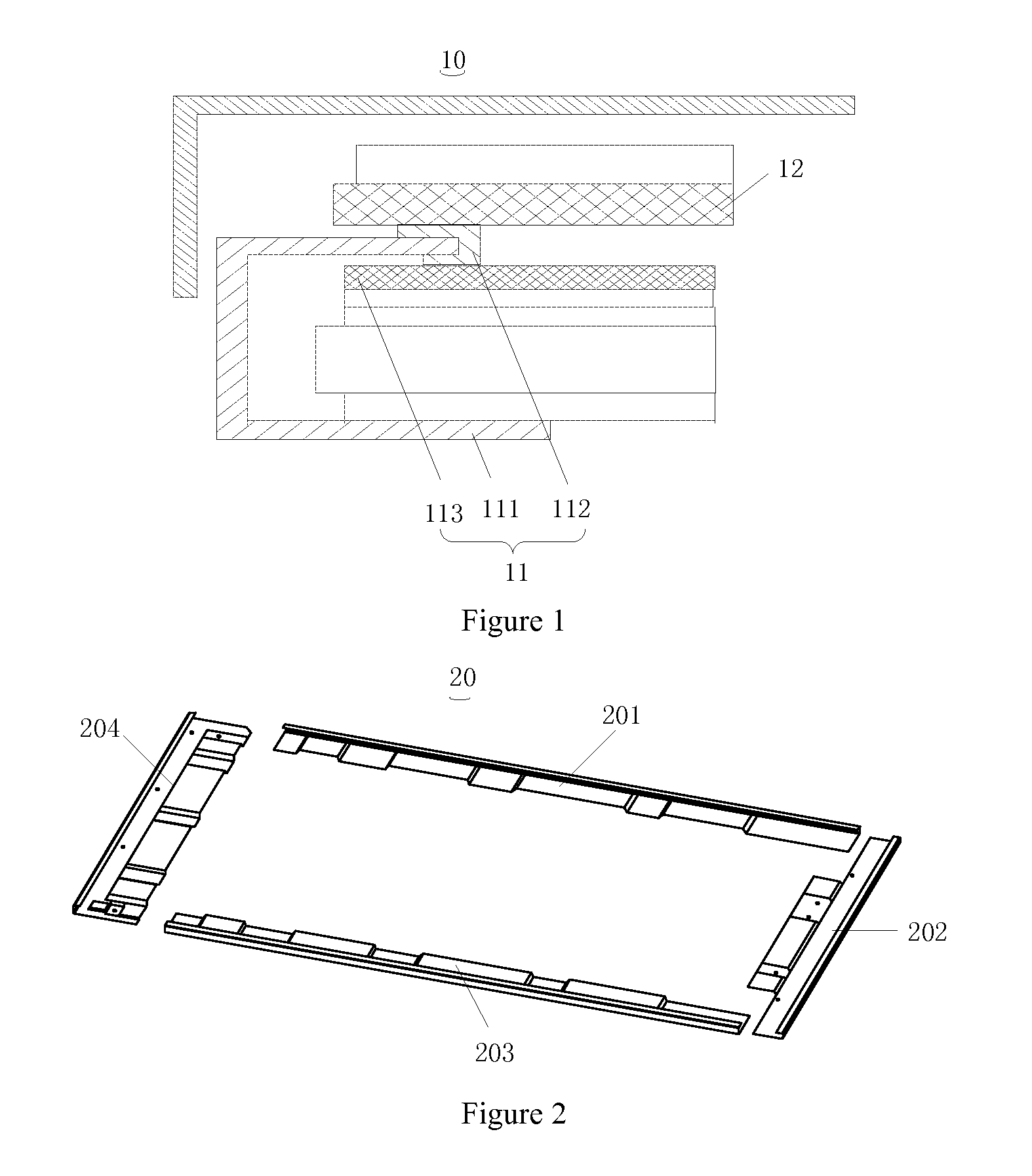
[0034]The main connecting members may be assembled by latches, screws, weld, or glue. As shown in FIG. 2, the backlight system 20 may include four main connecting members. In one embodiment, the main connecting members include a first connecting member 201, a second connecting member 202, a third connecting member 203, and a fourth connecting member 204. The four main connecting members are substantially bar-shaped, and front ends...


PUM


Abstract

A backlight system and the liquid crystal device are disclosed. The backlight system includes a back plate, optical films and a protecting member. The back plate includes at least two main connecting members, and at least one main connecting member includes a top plate and a down plate. The protecting member includes a first portion and a second portion. The protecting member is fixed on the top plate so that the first portion is arranged above the top plate to separate the top plate and the liquid crystal panel above the top plate. The second portion is arranged on a down surface of the top plate to separate the top plate and the optical films. In this way, the assembling efficiency is high and the labor cost is low. In addition, the risk of scratching the liquid crystal panels and the optical films during the assembling process of the backlight system is also reduced.

Description

BACKGROUND OF THE INVENTION[0001]1. Field of the Invention[0002]Embodiments of the present disclosure relate to display technology, and more particularly to a backlight system and the liquid crystal device with the same.[0003]2. Discussion of the Related Art[0004]Liquid crystal devices include back plates, reflective sheets, optical films, plastic frames, display panels and front frames. Currently, integrally formed back plates are assembled with liquid crystal display modules by manual processes. The assembly processes of the backlight system of the liquid crystal display module includes disposing the integrally formed back plate flatly, fixing the reflective sheet on the back plate, and assembling the reflective sheet and the optical film with the back plate in turn. The remaining steps include disposing the plastic frame, disposing the display panel on the plastic frame, disposing the front frame, and assembling the front frame and the back plate. It is obvious that a lot of manu...

Claims


Application Information

Patent Timeline
IPC IPC(8): G09F13/04
CPCG09F13/0413G02B6/0088G02B6/0093G02F1/133308G02F2201/503G02F1/133314G02F1/133317
Inventor KUO, YI-CHENGHSIAO, YU-CHUNQUE, CHENGWENZHANG, PANGLINGLI, DEHUA
Owner TCL CHINA STAR OPTOELECTRONICS TECH CO LTD
Why Eureka
Try Eureka