Pedometer

Inactive Publication Date: 2009-10-29
SEIKO INSTR INC
View PDF9 Cites 93 Cited by
  • Summary
  • Abstract
  • Description
  • Claims
  • Application Information

AI Technical Summary

Benefits of technology

[0013]According to the pedometer of the embodiment of the invention, power saving

Problems solved by technology

However, it is necessary to provide a switch to detect the opening and closing of the pedometer case cover, or a switch to detect that the pedometer is worn on the garment, which leads to a problem of cost i

Method used


Image

  • Pedometer
  • Pedometer
  • Pedometer

Examples


Embodiment Construction

[0020]Hereinafter, a pedometer according to an embodiment of the invention will be described with reference to the drawings. In addition, in each drawing, the same components are designated the same numerals and signs.

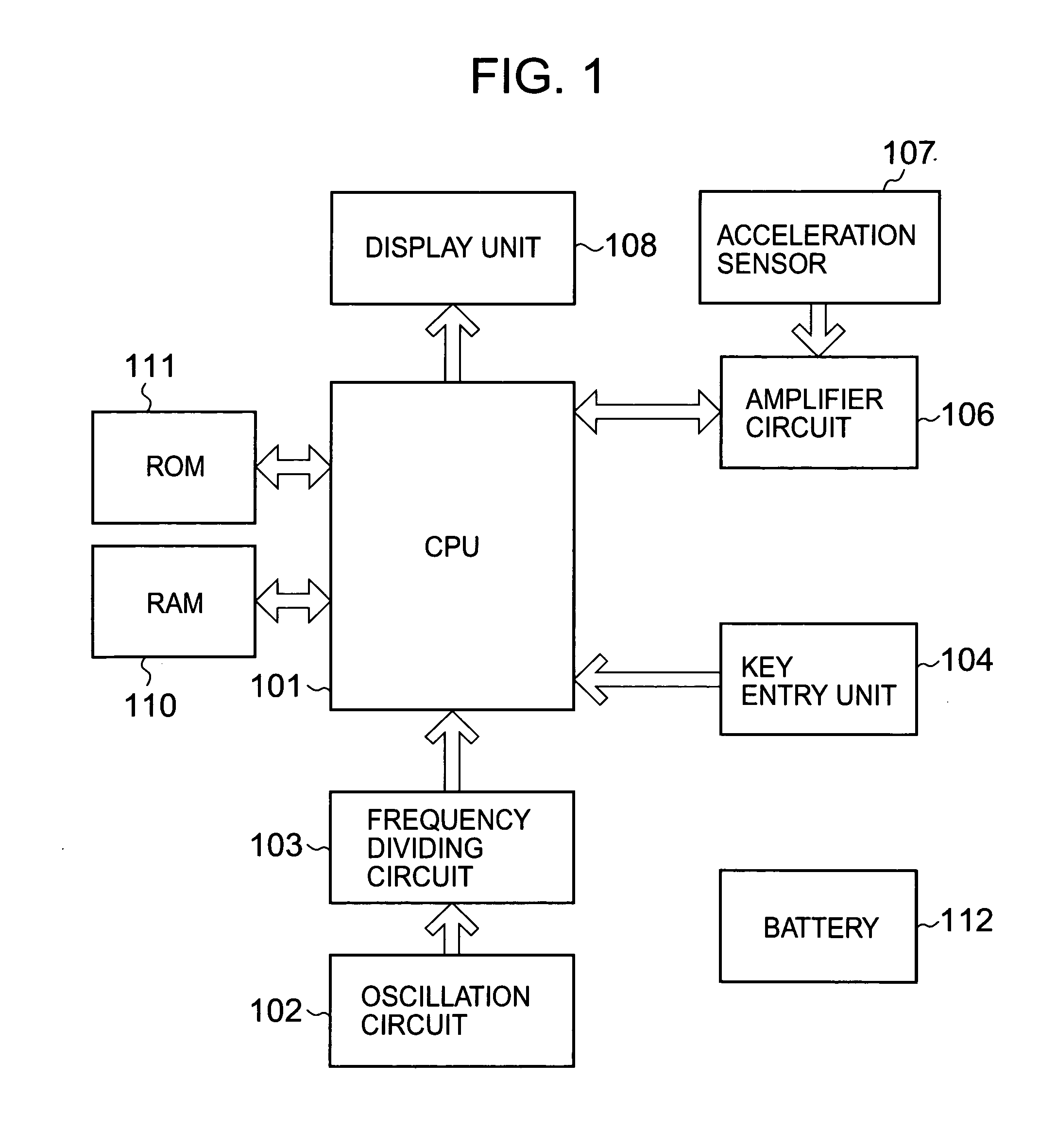
[0021]FIG. 1 is a block diagram depicting a pedometer according to an embodiment of the invention.

[0022]In FIG. 1, the pedometer has a central processing unit (CPU) 101, an oscillation circuit 102 that outputs a signal at a predetermined frequency, a frequency dividing circuit 103 that divides the output signal from the oscillation circuit 102 by a predetermined divide ratio to output a clock signal for measuring time, a key entry unit 104 configured of a switch externally operable, an acceleration sensor 107 that detects that a user is taking a step (including running) to output a signal (walking signal) corresponding to the step, and an amplifier circuit 106 that amplifies and outputs the walking signal outputted from the acceleration sensor 107.

[0023]In addition, th...


PUM


Abstract

Power savings are aimed by controlling display of a step count with no additional hardware. An acceleration sensor detects that a user is taking a step through an amplifier circuit, and outputs a walking signal corresponding to the step to a CPU. The CPU counts walking signals, and displays the accumulated number of steps on a display unit. When the CPU determines that the user is taking steps based on the walking signals, the CPU stops drive power from a battery to the display unit, and controls the display unit to stop displaying a step count.

Description

BACKGROUND OF THE INVENTION[0001]1. Field of the Invention[0002]The present invention relates to a pedometer, which detects that a user is taking steps and counts the steps.[0003]2. Description of the Related Art[0004]Heretofore, pedometers are utilized, one of which is mounted on the hips of a user for use, or is placed in a bag and a user carries the bag for use, and then a sensor detects that the user is taking steps for counting the steps.[0005]Generally, because users rarely see the indications of a pedometer while walking, it is proposed that a state of closing a pedometer case cover is detected, or a state of wearing a pedometer on a garment is detected to turn out the light for the indications to provide power savings (for example, see Patent Documents, JP-A-57-48176 and JP-A-2007-307218).[0006]However, it is necessary to provide a switch to detect the opening and closing of the pedometer case cover, or a switch to detect that the pedometer is worn on the garment, which lead...

Claims


Application Information

Patent Timeline
IPC IPC(8): G01C22/00G06F15/00
CPCG01C22/006
Inventor SUGAI, YOSHINORI
Owner SEIKO INSTR INC
Why Eureka
Try Eureka