Slicing and dicing device

a dicing device and dicing blade technology, applied in the field of dicing devices, can solve the problems of increasing the cost of the device, too large device, and substantial effort required

Inactive Publication Date: 2009-11-05
HOOD LANCE +1
View PDF31 Cites 18 Cited by
  • Summary
  • Abstract
  • Description
  • Claims
  • Application Information

AI Technical Summary

Benefits of technology

[0008]It is a further object to provide such a device which also is...

Problems solved by technology

Since a large number of slicing cuts into the item are made simultaneously, a substantial effort is required.
Long levers are sometimes employ...

Method used


Image

  • Slicing and dicing device
  • Slicing and dicing device
  • Slicing and dicing device

Examples


Embodiment Construction

[0034]In the following detailed description, certain specific terminology will be employed for the sake of clarity and a particular embodiment described in accordance with the requirements of 35 USC 112, but it is to be understood that the same is not intended to be limiting and should not be so construed inasmuch as the invention is capable of taking many forms and variations within the scope of the appended claims.

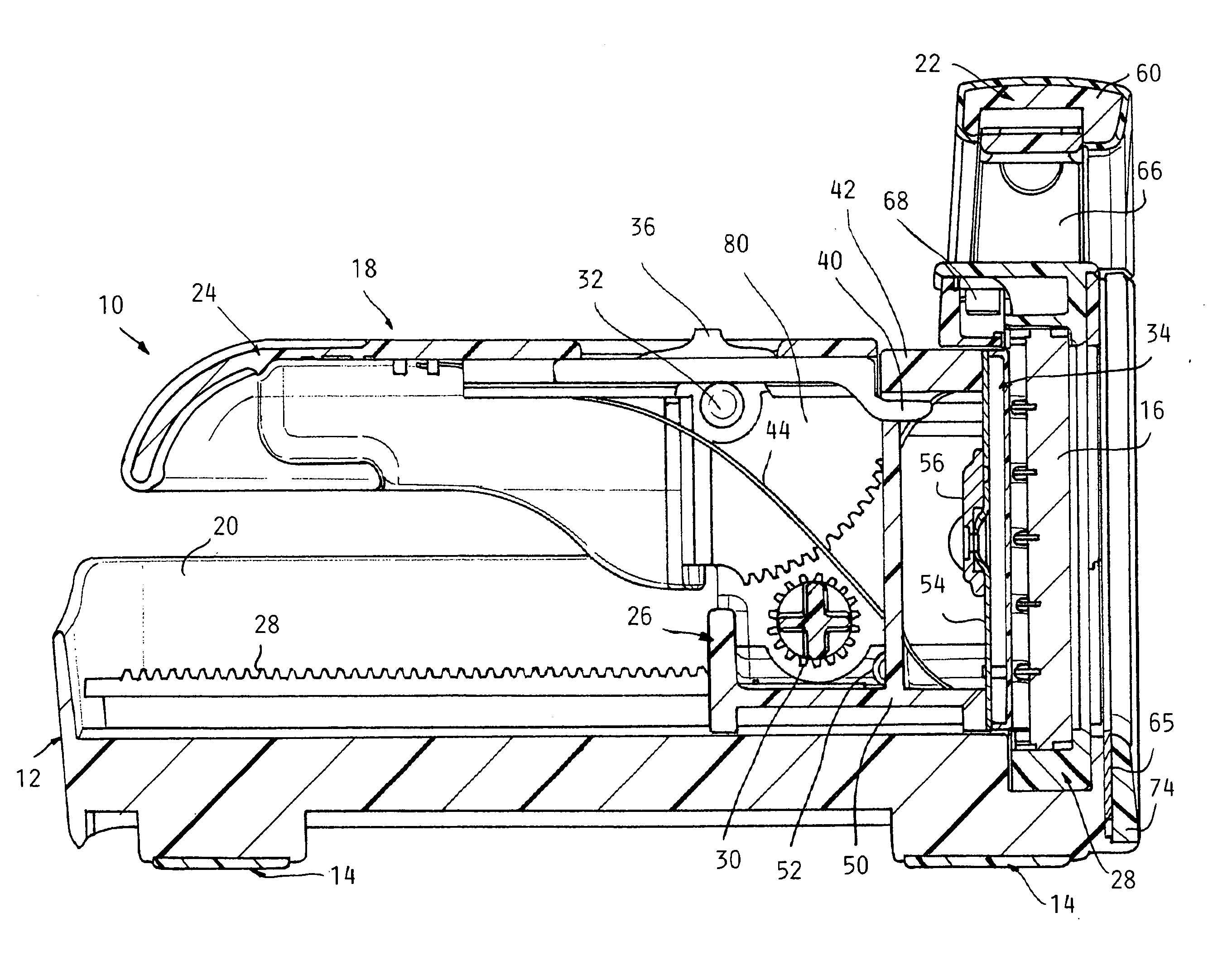
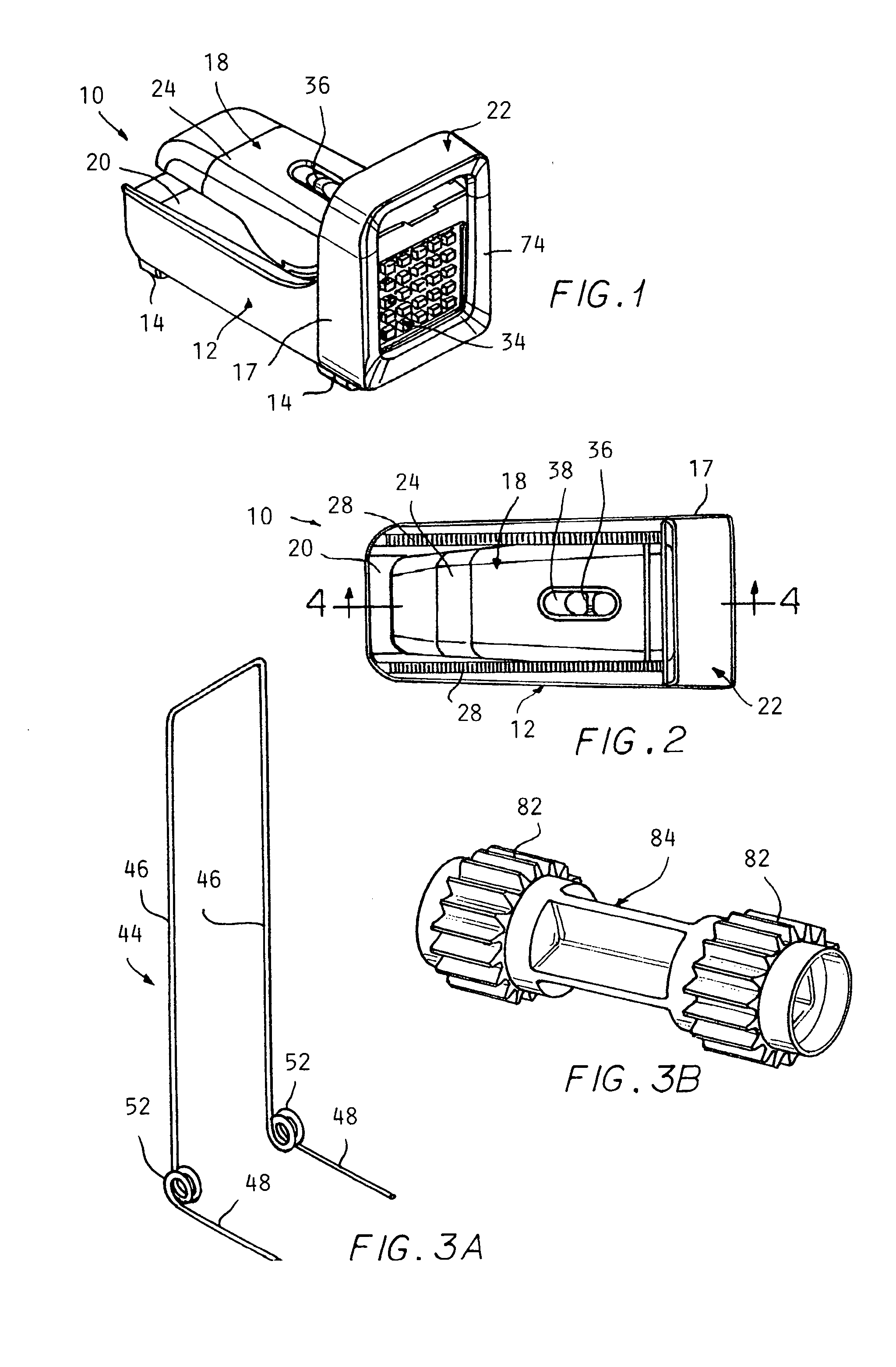
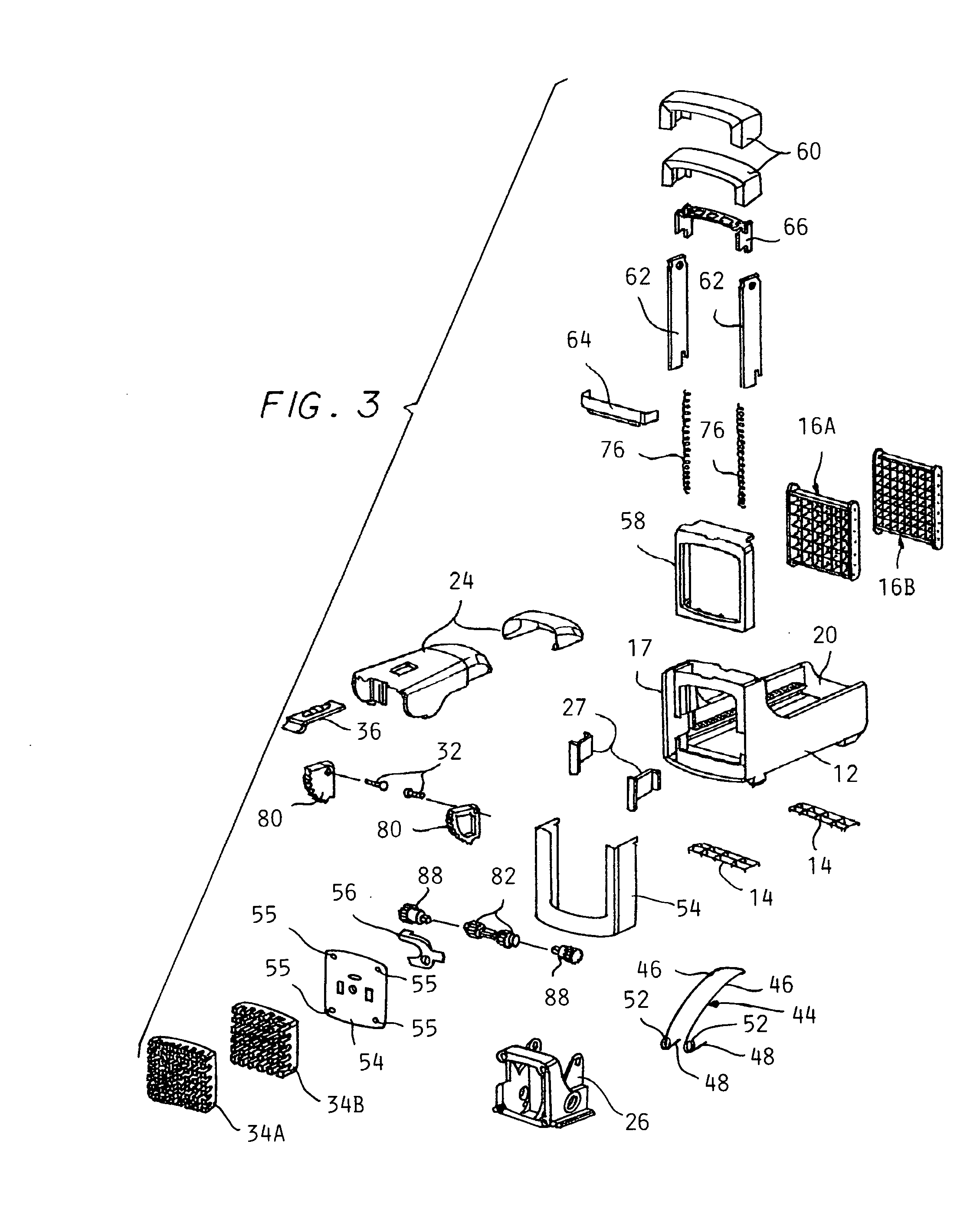
[0035]Referring to the drawings and particularly claims 1 and 2, a slicing and dicing device 10 in a stored condition according to the invention. The device 10 includes a main body 12 supported on feet 14.

[0036]A cutting grid 16 is supported at an upright front end 17 of the main body with plugs of a pusher face 24 of a pusher assembly 18 protruding through spaces in the cutter grid 16.

[0037]The main body 12 includes a pusher assembly 18 supported on a bed 20 defined by the main body 12 to the rear of the front end 17.

[0038]FIG. 1 show the pusher assembly 18 in its stora...


PUM

PropertyMeasurementUnit
Pressureaaaaaaaaaa

Abstract

A slicing and dicing device which includes a pivoted lever which when stroked slides a pusher assembly partway along on a main body towards a cutter piece to slice an interposed item. Gearing operated by the lever disengages after each stroke to allow another stroke, reducing the peak effect required by limiting the range of motion to a range where good leverage is obtained. A dicing assembly is mounted forward of the cutter piece for vertical sliding motion to allow cross cutting of strips sliced out of the item by the cutter piece.

Description

CROSS REFERENCE TO RELATED APPLICATIONS[0001]This application claims the benefit of U.S. provisional application No. 61 / 000,504 filed on Oct. 26, 2007.BACKGROUND OF THE INVENTION[0002]This invention concerns slicing of vegetables or fruits such as potatoes into strips (i.e., french fries) or diced into cubes. There has heretofore been provided “potato chippers” which operate to force a potato (or other fruit or vegetable) through a cutter grid to slice the same into strips such as create french fries from a whole potato.[0003]A lever is manually pivoted through a single stroke which causes the item to be advanced by engagement of a pusher face having a pattern of plugs which fit into the cutter grid when the pusher face is fully advanced.[0004]Since a large number of slicing cuts into the item are made simultaneously, a substantial effort is required. The lever typically pivots through a range of 90° from a fully upright position, and the leverage able to be exerted by the user vari...

Claims


Application Information

Patent Timeline
IPC IPC(8): A47J43/04B26D7/06
CPCB26D1/553B26D3/185B26D9/00B26D7/0608B26D5/10Y10T83/662Y10T83/6662Y10T83/6664
Inventor HOOD, LANCESTEWART, JOSHUA R.
Owner HOOD LANCE
Why Eureka
Try Eureka