Weaving Machine Comprising Pneumatic Weft Insertion

Inactive Publication Date: 2009-11-05
TEXTILMA AG
View PDF16 Cites 0 Cited by
  • Summary
  • Abstract
  • Description
  • Claims
  • Application Information

AI Technical Summary

Benefits of technology

[0007]Since the blow nozzles are mounted pivotably in the transverse direction toward the shears and are connected to a specific motor drive device, in order to move the selected blow nozzle toward the shears exactly, the inserted weft thread is cut virtually only when it enters the shears. It is thereby possible to shift the cutting off of the inserted weft thread into the beating-up region of the weft thread, so that there is no longer any need for a clamping device. This not only simplifies the weaving machine, but also increases the accuracy of insertion of the weft thread.
[0009]The accuracy and operating reliability of the weaving machine can be improved if the drive device is designed such that the blow nozzle used in each case is oriented in the transverse direction at least approximately coaxially to the guide duct.
[0010]Particularly when blow nozzles arranged one above the other in the vertical direction are used, the design according to which the blow nozzles are mounted pivotably and can be driven further in the vertical direction transversely to the transverse direction. This drive may take place in a known way by means of the Jacquard device. However, the design is more advantageous, according to which the blow nozzles are connected to a further separate motor drive device for the vertical direction, in order to align one of the blow nozzles at least approximately with the guide duct in the vertical direction. This refinement is advantageous particularly when the weft insertion device has a plurality of blow nozzles arranged in the transverse direction and in the vertical direction.

Problems solved by technology

In this case, the weft thread has already assumed a reliable position, so that, even after cutting off, a displacement of the weft thread is no longer possible.

Method used


Image

  • Weaving Machine Comprising Pneumatic Weft Insertion
  • Weaving Machine Comprising Pneumatic Weft Insertion
  • Weaving Machine Comprising Pneumatic Weft Insertion

Examples


Embodiment Construction

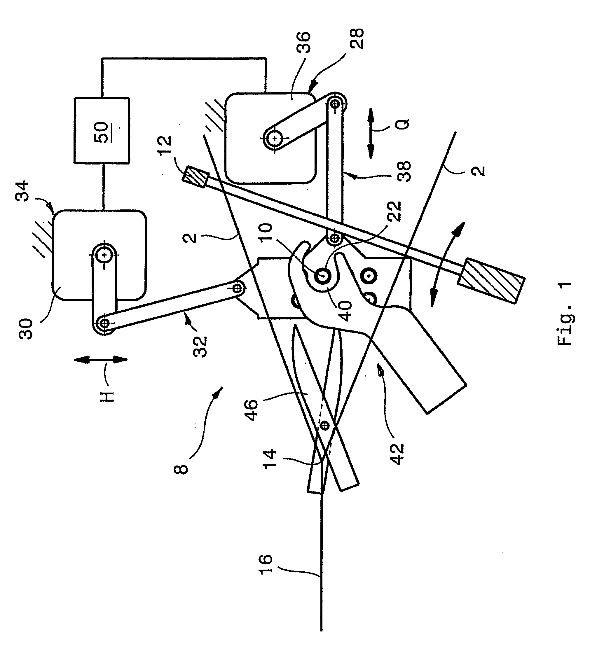
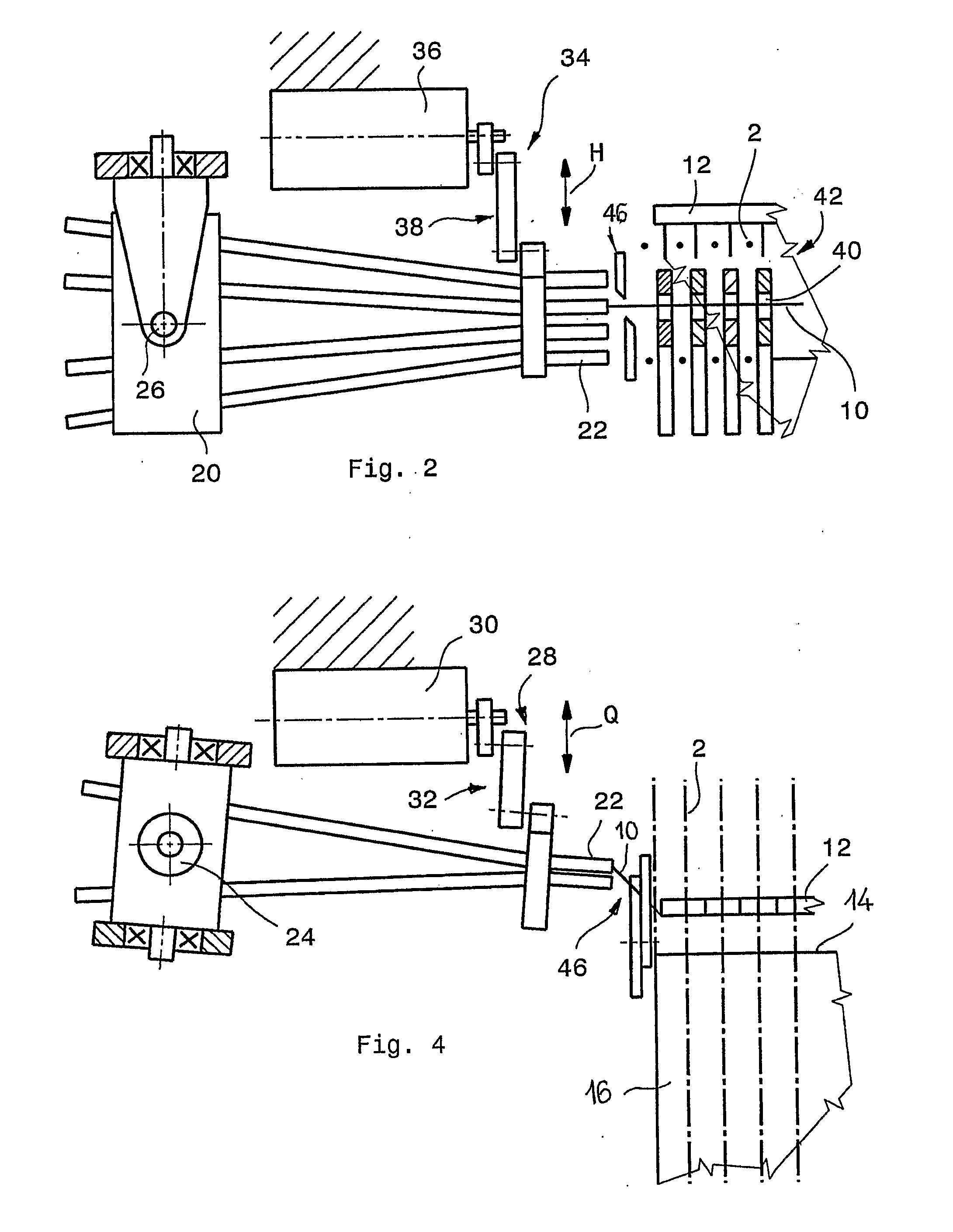
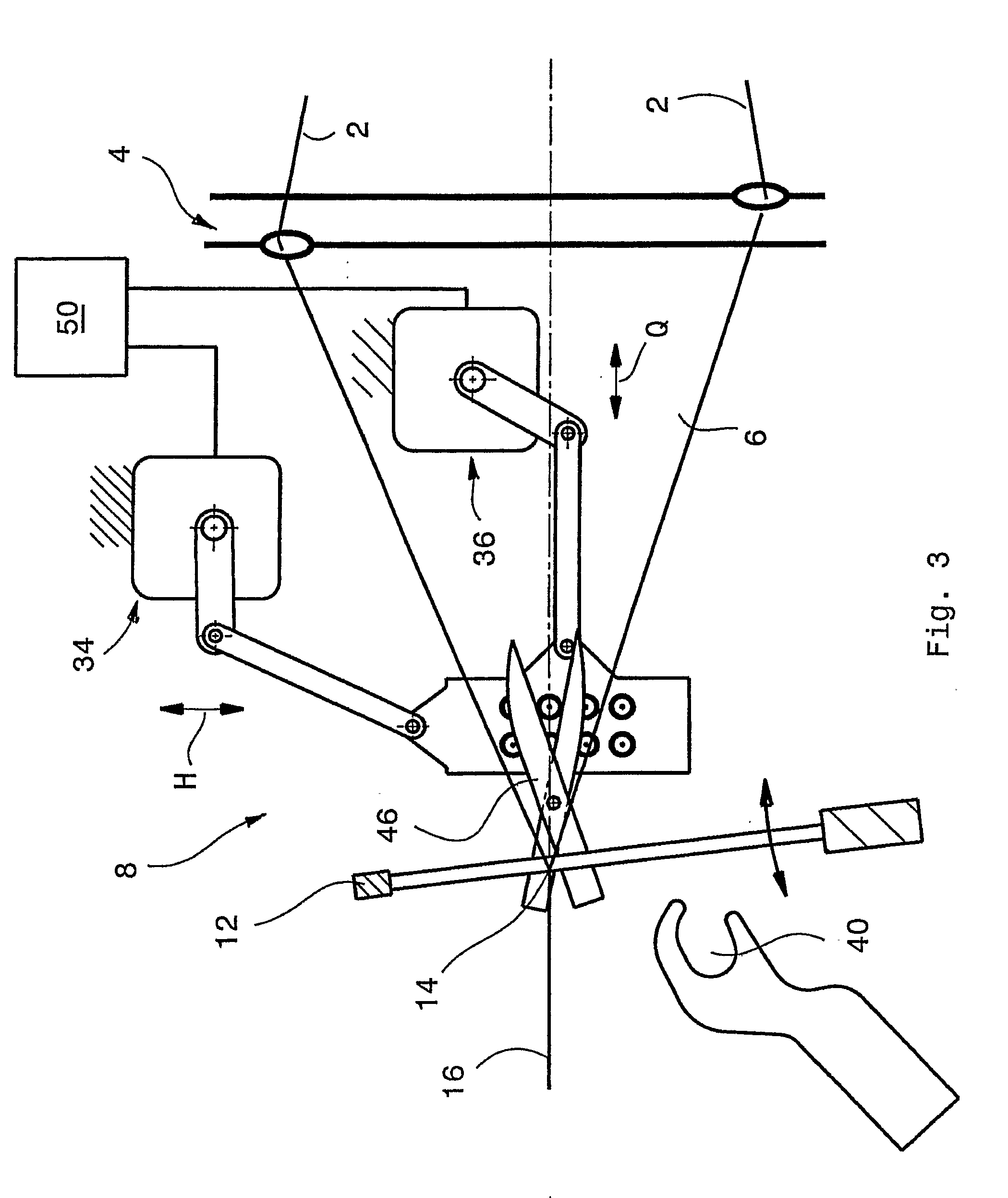
[0019]FIGS. 1 to 4 show the weft insertion region of a weaving machine in a diagrammatic illustration, only the parts important for the present invention being shown. All the other features of the weaving machine are state of the art.

[0020]FIGS. 1 and 3 show the weaving region of a weaving machine, at which warp threads 2 are moved by means of a shedding device 4, for example a Jacquard device, to an open shed 6, into which a weft thread 10 is inserted by means of a weft insertion device 8. By means of a reed 12, the weft thread 10 is beaten up at a beating-up edge 14, so that a cloth web 16 is obtained.

[0021]The weft insertion device 8 is designed pneumatically and has a nozzle block 20 which, in the present example, has eight blow nozzles 22 which, according to FIG. 4, are arranged in pairs in transverse direction Q, according to FIG. 2 four pairs of such blow nozzles being arranged one above the other in the vertical direction H. The nozzle block 22 is arranged pivotably via a ve...


PUM


Abstract

The weaving machine comprises a pneumatic weft insertion. It is fitted with a weaving reed (12), wherein a guiding device (42) is associated with a guiding channel (40) for a weft thread (10). The guiding channel (10) comprising the weaving reed (12) can be pivoted between an insertion position and a stop position for the weft thread (10). Also, a fixed weft thread insertion device (8), which comprises at least two blast nozzles (22), is associated with the guiding channel (40) in the insertion position. A fixed blade (46) is used to cut the inserted weft thread (10). The blast nozzles (22) are pivotably mounted in the transversal direction (Q) counter to the blade (46) in order to improve the weaving machine and are connected by means of a motor drive device (28) in order to displace the blast nozzles (22) counter to the blade (46).

Description

[0001]This application claims priority of PCT application PCT / CH2006 / 000340 having a priority date of Oct. 5, 2005, the disclosure of which is incorporated herein by reference.TECHNICAL FIELD[0002]The invention relates to a weaving machine comprising pneumatic weft insertion.BACKGROUND OF THE INVENTION[0003]A weaving machine comprising pneumatic weft insertion of the type initially mentioned is known, for example, from WO 97 / 13901. The weaving machine has a reed which is assigned a guide device with a guide duct for a weft thread. The guide duct is pivotable, together with the reed, between an insertion position and a beating-up position of the weft thread. Furthermore, the guide duct is assigned, in the insertion position, a fixed weft insertion device with blow nozzles, which is therefore independent of the reed and therefore, on the one hand, does not impair the movement of the reed and, on the other hand, is also not impaired itself by the movements of the reed. Shears serve for...

Claims


Application Information

Patent Timeline
IPC IPC(8): D03D47/30D03D47/36
CPCD03D47/3046D03D47/3013D03D47/30
Inventor SPEICH, FRANCISCOMEIER, ERWIN
Owner TEXTILMA AG
Why Eureka
Try Eureka