Exhaust gas turbocharger for an internal combustion engine

Inactive Publication Date: 2010-06-24
IHI CHARGING SYST INT +1
View PDF6 Cites 12 Cited by
  • Summary
  • Abstract
  • Description
  • Claims
  • Application Information

AI Technical Summary

Benefits of technology

[0007]Preferably, the spacer element is in the form of streamlined sleeve whereby material and weight can be reduced in an advantageous manner.
[0008]A flow resistance as small as possible can be adjusted in each operating point of the exhaust gas turbocharger by means of a mounting which can be moved in a rotatable or translational manner. In this way, the best possible efficiency can be achieved in each operating point of the exhaust gas turbocharger.
[0009]For further increase of the efficiency, the spacer element is positioned in such a manner that a first trailing wake line caused by the spacer element extends through a channel between a first guide vane and a second guide vane formed adjacent to the first guide vane without an interaction with a boundary layer of the second guide vane. A flow section which is formed downstream of an element flown over has principally to be called a trailing flow. The trailing flow is a flow section formed at the rear edge of a vane-shaped spacer element whose vane tips are arranged in the direction of the flow. This trailing flow influences the flow in the channel formed between two guide vanes. When the trailing flow reaches the boundary layer of a guide vane, the boundary layer becomes wider or is torn off which causes an efficiency loss. This tearing can be avoided by means of the suitable positioning of the spacer element, so that an efficiency increase can be obtained.

Problems solved by technology

Due to the positioning of the spacer elements in the inflow channel, a flow resistance is generated which is opposed to the exhaust gas inflow, whereby efficiency losses of the exhaust gas turbocharger are effected.

Method used


Image

  • Exhaust gas turbocharger for an internal combustion engine
  • Exhaust gas turbocharger for an internal combustion engine
  • Exhaust gas turbocharger for an internal combustion engine

Examples


Embodiment Construction

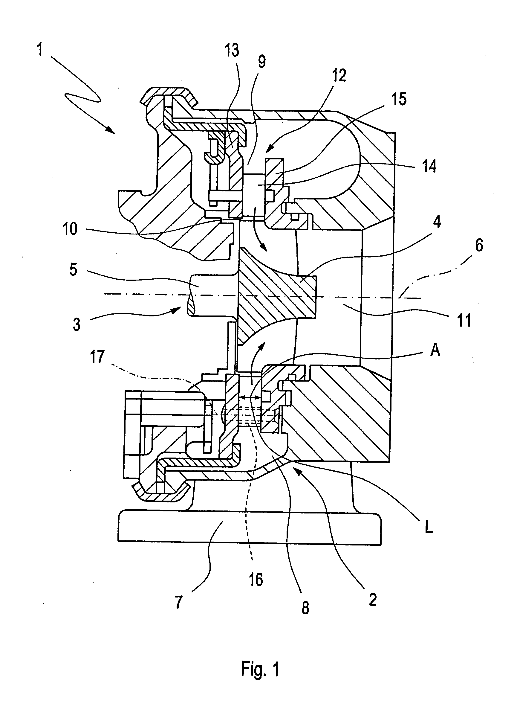
[0018]The exhaust gas guide section 2 of an exhaust gas turbocharger 1 through which the exhaust gas flows as shown in FIG. 1 is provided in an exhaust gas tract of an internal combustion engine, not shown in detail, which is a gasoline engine or a Diesel engine. The exhaust gas turbocharger 1 further has a fresh air compressor section, which is not shown but which is arranged in an intake tract of the internal combustion engine, not shown in detail.

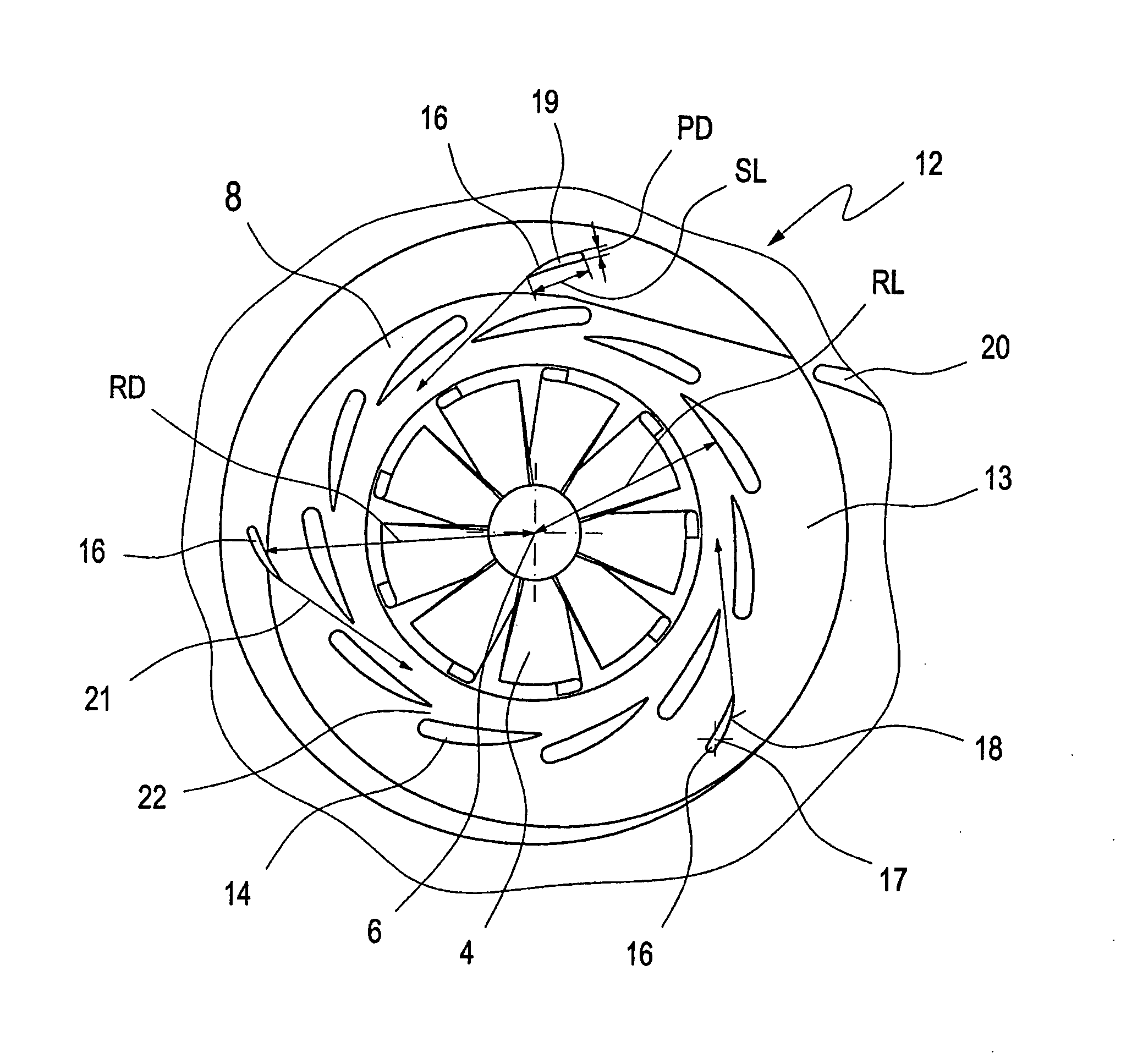
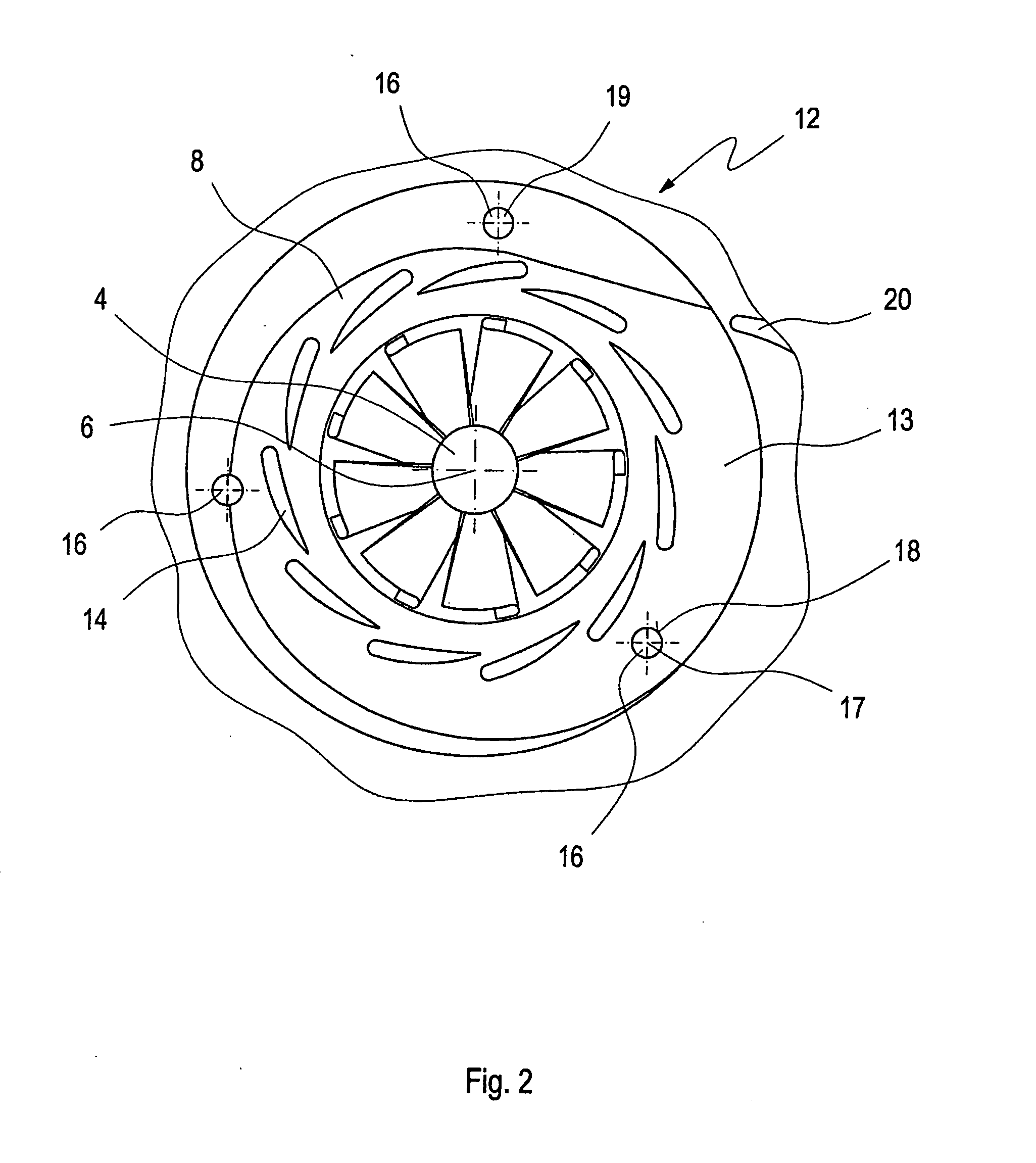
[0019]The exhaust gas turbocharger 1 has a rotor assembly 3 which comprises a compressor wheel for taking in and compressing combustion air but which is not shown, a turbine rotor 4 for the expansion of exhaust gas, and a shaft 5 with a rotational axis 6 connecting the compressor wheel to the turbine rotor 4 in a rotationally fixed manner. The shaft 5 is mounted rotatably in the bearing section of the exhaust gas turbocharger 1, which is positioned between the air guide section and the exhaust gas guide section 2.

[0020]An entry channel 7...


PUM


Abstract

In an exhaust gas turbocharger for an internal combustion engine, comprising a turbine rotor, which is rotatably housed in a rotor chamber through which exhaust gas coming from the internal combustion engine is conducted and wherein the flow around the turbine rotor is conditioned by means of a guide apparatus comprising a support ring with rotatably mounted guide vanes. For fixing a first distance (A) between the support ring and the contour sleeve, at least one spacer element with a longitudinal axis, an outer surface and a cross-sectional area is provided so as to have a streamlined shape forming in the exhaust gas flow only a relatively narrow wake line and the spacer element is so arranged that the wake line formed thereby extends essentially through a flow space between two adjacent guide vanes without disturbing the exhaust gas flow around these guide vanes.

Description

[0001]This is a Continuous-In-Part Application of pending international patent application PCT / EP2008 / 004807 filed Jun. 14, 2008 and claiming the priority of German patent application 10 2007 029 004.9 filed Jun. 23, 2007.BACKGROUND OF THE INVENTION[0002]The invention relates to an exhaust gas turbocharger for an internal combustion engine with an exhaust gas turbine including a rotor and a controllable exhaust gas guide section.[0003]DE 103 25 985 A1 discloses a guide apparatus in an exhaust gas guide section of an exhaust gas turbocharger for an internal combustion engine. A flow around the turbine rotor of exhaust gases exiting from the internal combustion engine can be altered by means of the guide apparatus. The guide apparatus has a number of adjustable guide vanes, which are positioned in an inflow channel in the exhaust gas guide section upstream of a rotor chamber in the exhaust gas guide section, in which the turbine rotor is received in a rotatable manner. The guide appar...

Claims


Application Information

Patent Timeline
IPC IPC(8): F02B33/34F04D29/44
CPCF01D17/165F05D2260/30F05D2220/40
Inventor EHRHARD, JAN
Owner IHI CHARGING SYST INT
Why Eureka
Try Eureka