

Conductive film and method of producing thereof
a conductive film and film technology, applied in the direction of conductive layers on insulating supports, photosensitive materials, instruments, etc., can solve the problems of erroneous operations and troubles, troublesome health of operators of such equipment, and increase in electromagnetic interference (emi) , to achieve the effect of low cost and high conductivity
- Summary
- Abstract
- Description
- Claims
- Application Information
AI Technical Summary
Benefits of technology
Problems solved by technology
Method used
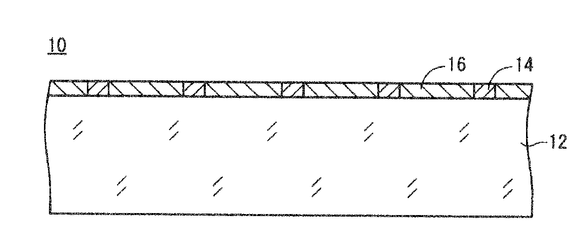
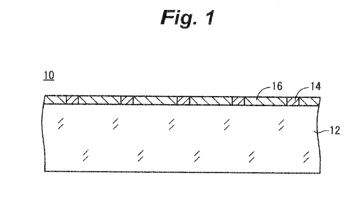
Image

Examples
example 1-1
Preparation of Emulsion A
[0178]To the following solution 1, while the temperature and the pH of which were kept at 38° C. and 4.5, respectively, the following solutions 2 and 3 (amounts corresponding to 90% of the respective solution amounts) were added simultaneously over a period of 20 minutes with being stirred. In this way, nucleus particles 0.16 μm in size were formed. Subsequently, the following solutions 4 and 5 were added thereto over a period of 8 minutes, and the rests of the solutions 2 and 3 (amounts corresponding to 10% of the respective solution amounts) were further added thereto over a period of 2 minutes so as to cause the particles to grow up to 0.21 μm in size. Furthermore, 0.15 g of potassium iodide was added thereto, and the resultant was aged for 5 minutes to end the formation of the particles.
Solution 1:
[0179]
Water750mlGelatin (phthalation-treated gelatin)20gSodium chloride3g1,3-Dimethylimidazolidine-2-thione20mgSodium benzenethiosulfonate10mgCitric acid0.7g
So...
example 1-2
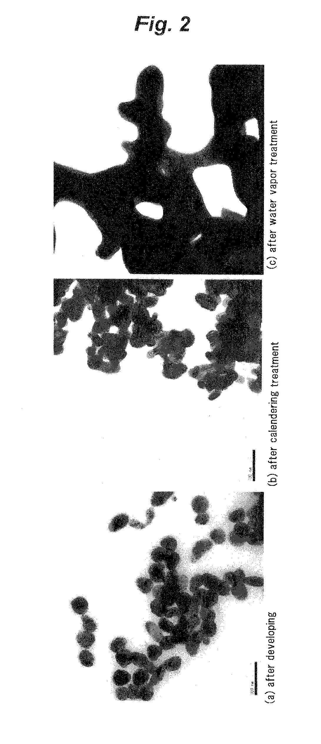
[0197]Samples prepared and subjected to exposing and developing treatments in the same way as in Example 1-1 were each subjected to a calendering treatment and a vapor contacting treatment. The calendering treatment was conducted in the same way as in Example 1-1 except that the load was changed.
[0198]Out of the resultant samples, one subjected to no calendering treatment and brought into contact with vapor for 30 seconds was named sample 1201; ones subjected to the calendering treatment with loads of 1,960 N / cm (200 kgf / cm), 2,940 N / cm (300 kgf / cm), 3,920 N / cm (400 kgf / cm), 5,880 N / cm (600 kgf / cm) and 6,860 N / cm (700 kgf / cm), respectively, and then brought into contact with vapor for 30 seconds were named sample 1202 to 1206, respectively; and ones brought into contact with vapor for 30 seconds and then subjected to the calendering treatment with loads of 1,960 N / cm (200 kgf / cm), 2,940 N / cm (300 kgf / cm), 3,920 N / cm (400 kgf / cm), 5,880 N / cm (600 kgf / cm) and 6,860 N / cm (700 kgf / cm), ...
example 1-3
[0204]Samples prepared and subjected to exposing and developing treatments and calendering treatment in the same way as in Example 1-1 were each subjected to a vapor contacting treatment as follows: the vapor contacting treatment was conducted in the same way as in Example 1-1 except that the vapor temperature was changed.
[0205]Out of the resultant samples, one treated at 80° C. was named sample 1301, one treated at 90° C. was named sample 1302, one treated at 100° C. was named sample 1303, one treated at 110° C. was named sample 1304, one treated at 120° C. was named sample 1305, and one treated at 130° C. was named sample 1306.
[0206]With respect to each of the samples, the surface resistance thereof was measured in the same way as in Example 1-1 before and after the vapor contacting treatment. The width of lines of the lattice pattern was measured in the same way as in Example 1-2. The results are shown in Table 3 below.
TABLE 3SurfaceSurfaceresistanceresistanceTemperaturebefore va...
PUM
| Property | Measurement | Unit |
|---|---|---|
| Temperature | aaaaa | aaaaa |
| Temperature | aaaaa | aaaaa |
| Temperature | aaaaa | aaaaa |
Abstract
Description
Claims
Application Information