
Method of correcting streaks using exposure modulation and spatially varying trcs

a technology of exposure modulation and spatial variation, applied in the field of printing machines and methods, can solve problems such as cross-process non-uniformities, undesirable visible color shift for overlaid colors, and subsystem defects in xerographic systems

Inactive Publication Date: 2009-11-05
XEROX CORP
View PDF24 Cites 18 Cited by
  • Summary
  • Abstract
  • Description
  • Claims
  • Application Information

AI Technical Summary

Benefits of technology

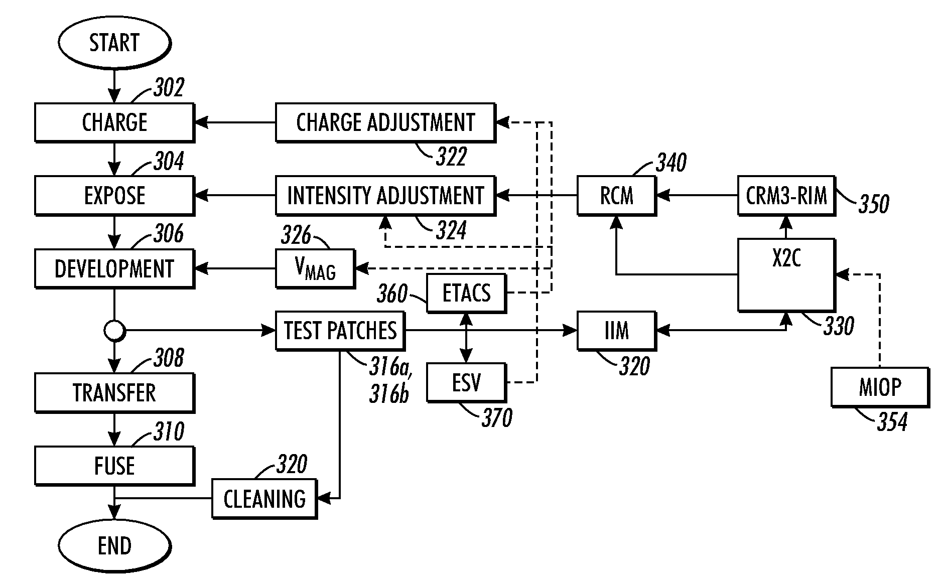
The patent describes a system and method for improving the quality of images produced by a digital printer. It uses a scanner to measure the cross-process reflectance of test images on the photoreceptor, and then generates both low and high frequency corrections to address streaks in the final image. The system includes a controller that generates the necessary compensation parameters for the raster output scanner and the spatially varying tone reproduction curve actuator. The technical effect of this patent is to provide a more accurate and precise method for compensating for streaks in images produced by a digital printer.

Problems solved by technology

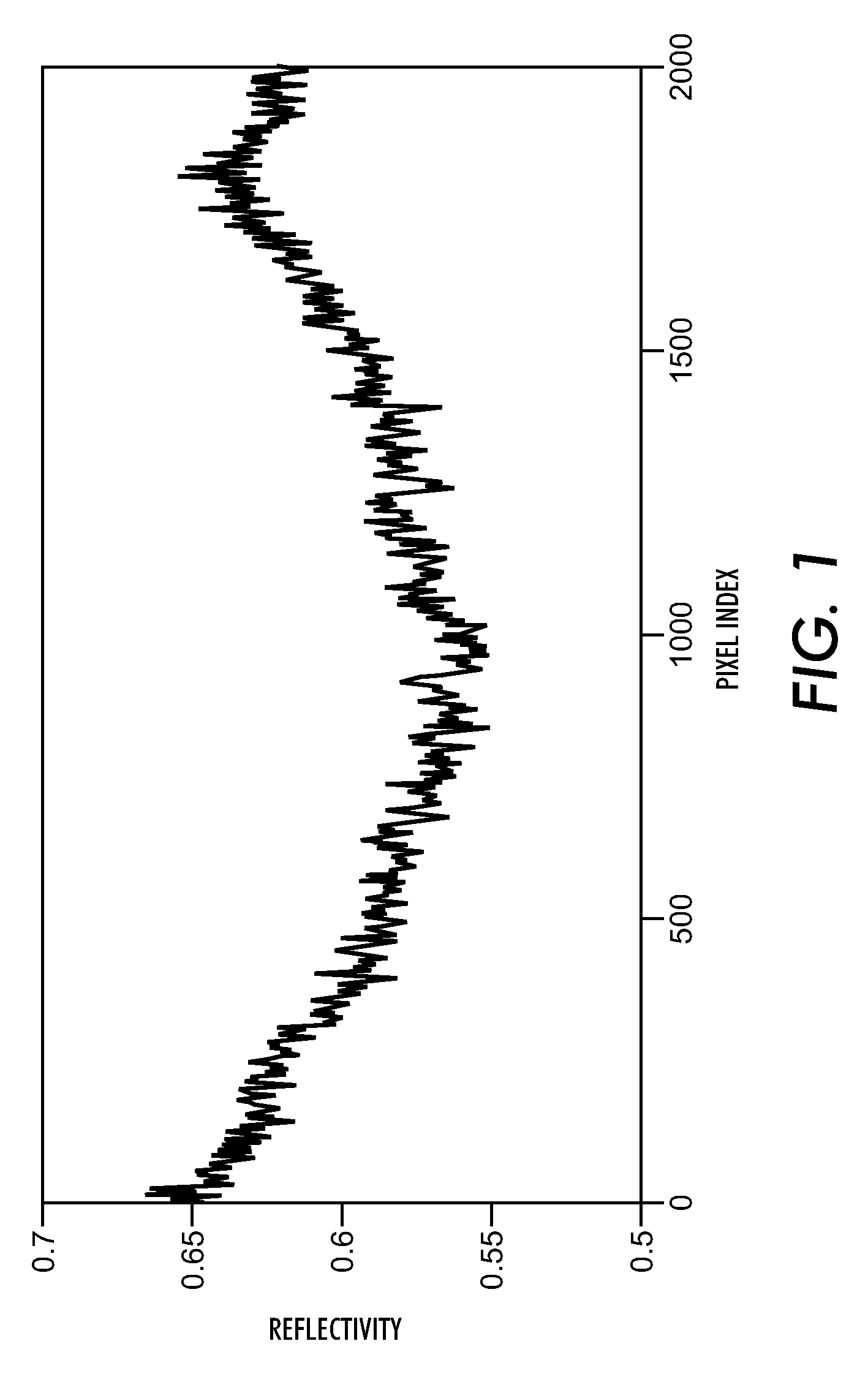
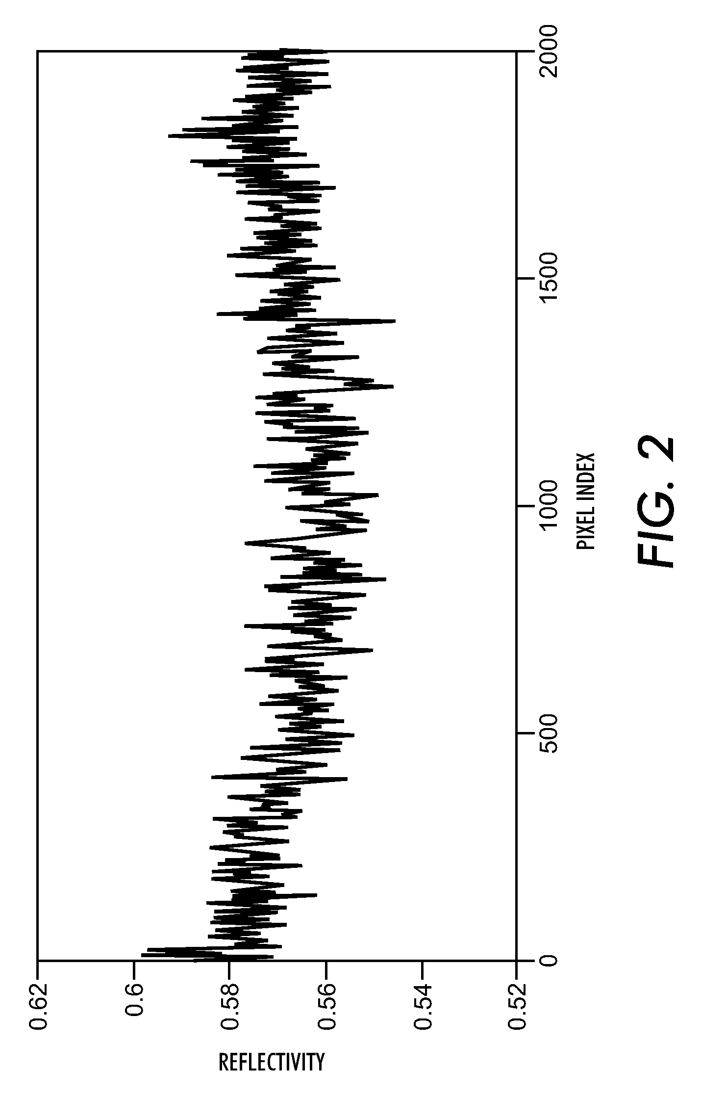
Although these xerographic printing machines usually produce a faithful reproduction of the original image, defects in the subsystems of the xerographic system may give rise to cross-process non-uniformities, commonly referred to as streaks or streak defects, which can be a significant factor effecting the overall image quality of the print.
In a color xerographic machine, streaks in single color separations that may be unobjectionable can cause an undesirable visible color shift for overlaid colors.
Conventional printing technologies contain several sources of streaks which cannot be satisfactorily controlled via printer design or printing system optimization.
Streaks can be caused by “non-ideal” responses of xerographic components in the marking engine.
Streaks can also be caused by non-uniformity of the raster output scanning device spot-size or intensity variations.

Method used


Image

  • Method of correcting streaks using exposure modulation and spatially varying trcs
  • Method of correcting streaks using exposure modulation and spatially varying trcs
  • Method of correcting streaks using exposure modulation and spatially varying trcs

Examples


Embodiment Construction

[0027]Exemplary embodiments shall be described for systems and methods of correcting non-uniformities, or streaks, in images formed by a xerographic image forming device in which low spatial frequency large amplitude defects are corrected using modulation of a raster output scanner, and high spatial frequency defects, as well as any residual low frequency defects are corrected using spatially varying tone reproduction curves.

[0028]With reference to FIGS. 4 and 5, a printing machine is illustrated generally at 8 according to an exemplary embodiment of this disclosure. The printing machine 8 is a single pass multi-color digital printer, also known as a xerographic or electrophotographic image forming device. The digital printer 8 described herein is a Xerox iGen3™ Digital Production Press and is provided by way of example, it should be appreciated that the systems and methods for compensating for image streaks, described herein, are suitable for use in other image forming devices.

[002...


PUM


Abstract

Systems and methods are provided for compensating for streak defects in images formed by an image forming device, such as a digital printer. The systems and methods include using both modulation of a raster output scanner (ROS actuation) and spatially varying tone reproduction curve (STRC actuation) in a common control system for improving streak correction. Low spatial frequency large amplitude streak defects are corrected using ROS actuation and high spatial frequency streak defects, as well as any residual low frequency defects, are corrected using STRC actuation.

Description

CROSS REFERENCE TO RELATED PATENTS AND APPLICATIONS[0001]U.S. patent application Ser. No. 11 / 702,238, by Wing et al., filed Feb. 5, 2007, entitled “PRINTING APPARATUS AND METHOD” is incorporated herein by reference in its entirety.BACKGROUND[0002]This disclosure relates to a printing machine and method. Specifically, the disclosed printing machine and method relate to scanning a P / R (Photoreceptor Belt) for image non-uniformities and controlling the printing process to reduce or correct the image non-uniformities. The present systems and methods relate to the field of digital imaging and, more particularly, to a system and method compensating for streaks and other image artifacts that appear on images which run parallel to the printer's process direction by using a combination of ROS actuation and spatially varying TRC actuation.[0003]A typical electrophotographic, or xerographic, printing machine employs a photoreceptor, that is charged to a substantially uniform potential so as to...

Claims


Application Information

Patent Timeline
Patent Type & Authority Applications(United States)
IPC IPC(8): H04N1/409
CPCG03G2215/00042H04N1/12G03G15/5041H04N1/4015H04N1/4076H04N1/295
Inventor VITURRO, R. ENRIQUEPAUL, PETER
Owner XEROX CORP
Learn More