
Hair trimmer with suction unit

a hair trimmer and suction unit technology, applied in the field of hair trimmers, to achieve the effect of increasing the speed of the fan, and increasing the suction power

Inactive Publication Date: 2009-11-12
KONINKLIJKE PHILIPS ELECTRONICS NV
View PDF10 Cites 12 Cited by
  • Summary
  • Abstract
  • Description
  • Claims
  • Application Information

AI Technical Summary

Benefits of technology

[0008]Such a hair trimmer having two different motors, one for the cutting unit and one for the suction unit, allows to choose different driving modes for the suction unit independently from the operation of the cutting unit. The different driving modes for the suction unit have the important advantage to allow for different suction power to be chosen from the user of the hair trimmer adapted to the length, thickness and number of the clippings to be collected. Thus, an efficient collection of clippings is ensured in all situations.
[0009]Higher suction power has usually the consequence of higher energy consumption and sometimes other nuisances like higher noise. The possibility of choosing a higher suction power only, when it is actually needed, has the advantage of allowing a minimization of energy consumption and of noise despite of providing the necessary suction power.
[0011]In preferred embodiments of the present invention, the suction unit comprises a fan that is driven by the second motor. The fan transports air, thus generating a vacuum to suck the clippings together with the air taken in by the fan. A suction unit based on a fan has the advantage to be comparatively inexpensive. It does not need too much space and is therefore simply implemented inside a hair trimmer.
[0012]Advantageously, the second motor is operable at different values of revolutions per minute. By operating the motor of the suction unit at different values of revolution, different suction powers can be achieved. Particularly in the case of a suction system based on a fan, the speed of the fan is increased by higher values of revolutions per minute of the driving motor. The higher the speed of the fan, the higher is the resulting suction power.
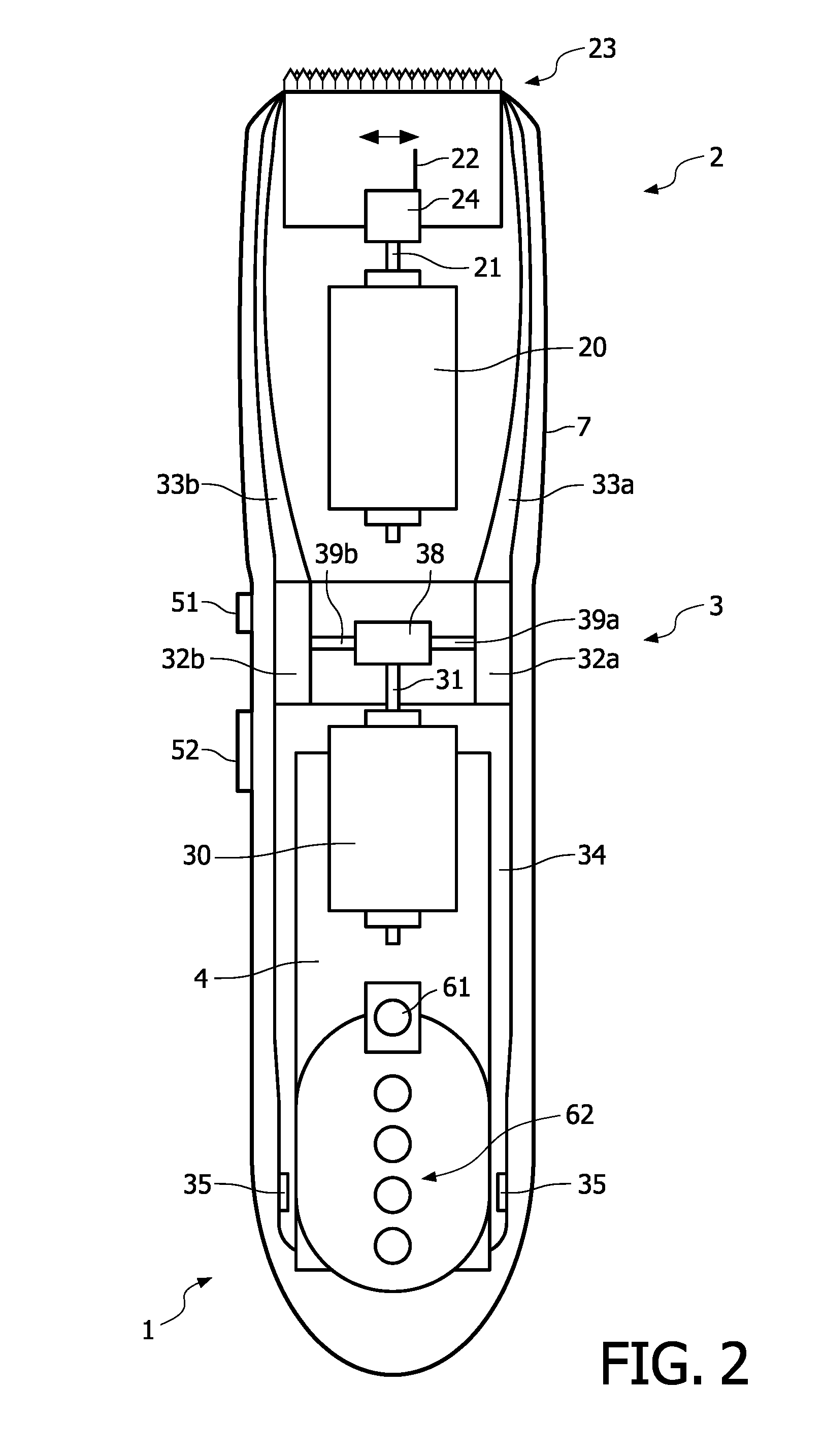
[0013]In a preferred embodiment of the present invention, the suction unit comprises two radial fans that are driven by the second motor. This embodiment provides the advantage of making possible to arrange for a certain geometric disposition of the suction power by having two suction streams. This allows further improving the efficiency of sucking and collecting the clippings.
[0014]The hair trimmer preferably comprises a receptacle to collect hair clippings, this receptacle being arranged in suction direction before the fan. As the hair clippings do not reach the fan, less maintenance of the fan is necessary, thus improving the ease-of-use and the lifetime of the hair trimmer.

Problems solved by technology

Higher suction power has usually the consequence of higher energy consumption and sometimes other nuisances like higher noise.

Method used


Image

  • Hair trimmer with suction unit
  • Hair trimmer with suction unit
  • Hair trimmer with suction unit

Examples


Embodiment Construction

[0022]The present invention will be explained more in detail with respect to a beard trimmer 1. But it will be noticed that the present invention may as well be implemented in any device designed for cutting or trimming, such as e.g. clippers or shavers.

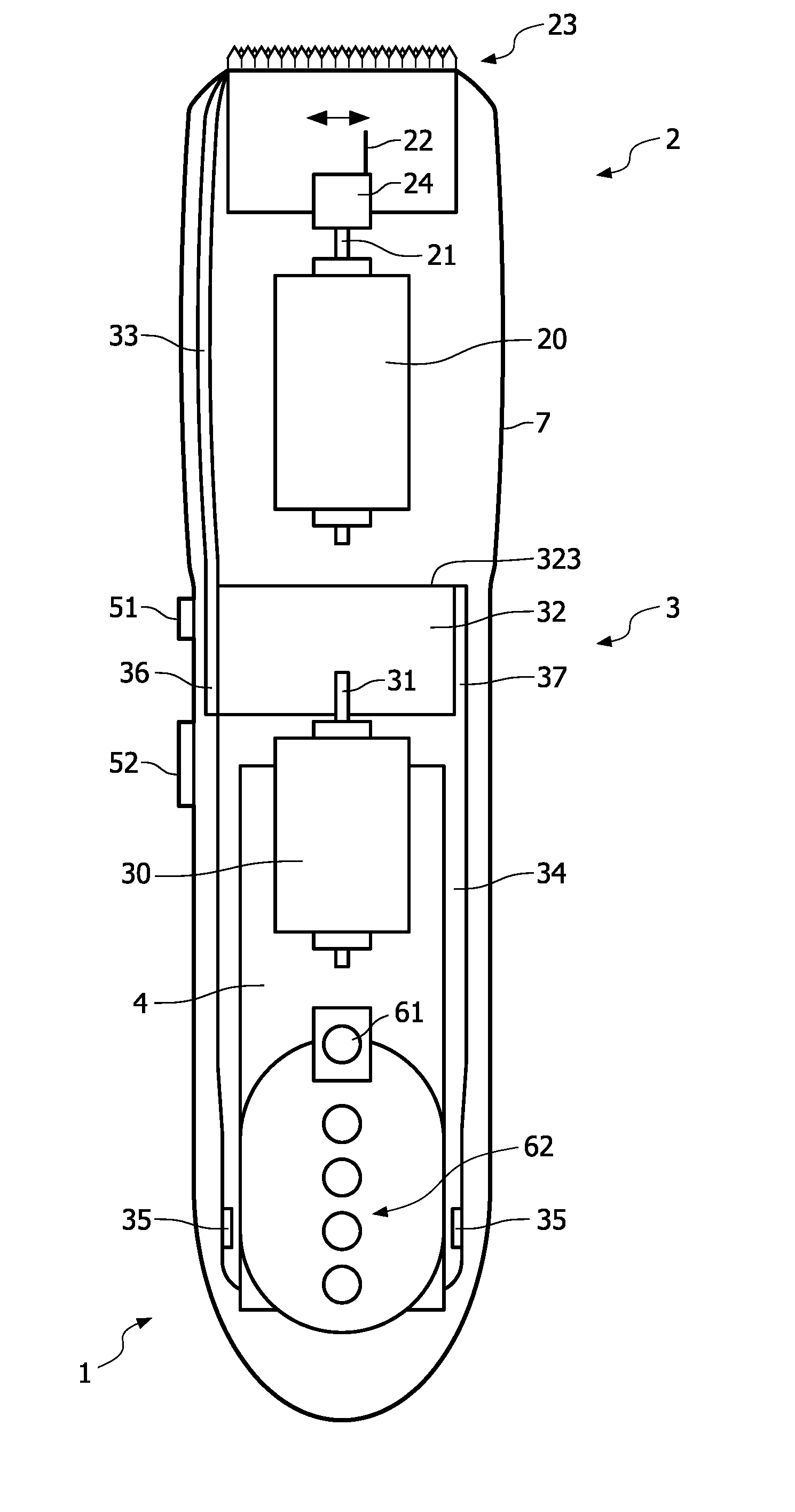
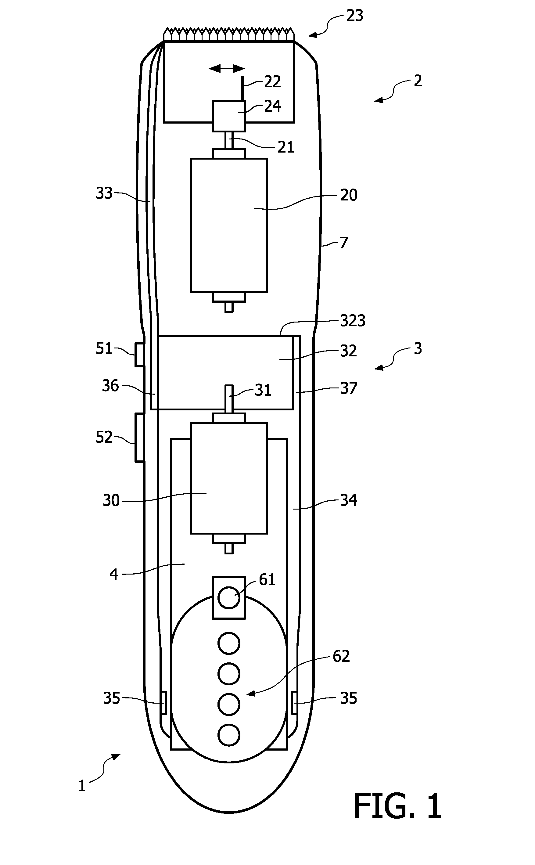
[0023]FIG. 1 shows schematically a first embodiment of a beard trimmer 1 comprising a cutting unit 2 and a suction unit 3, both housed in a casing 7. The main components of the cutting unit 2 are an electric motor 20 driving in well-known fashion reciprocating blades 23 with the help of a spindle 21, a gearing 24 and a shaft 22. The direction of the reciprocating movement is indicated by the double arrow.

[0024]The electric motor 20 is powered by a reloadable battery 4 and can be switched on or off by pressing the switch 51. The lamp 61 indicates whether the electric motor 20 is switched on or not.

[0025]As is well known by the person skilled in the art, one of the blades 23 is stationary and the other of the blades 23 is moving in a r...


PUM


Abstract

To improve the ease of use, a hair trimmer (1) is proposed, this hair trimmer (1) comprising a cutting unit (2) for trimming hair driven by a first motor (20) and a suction unit (3) for absorbing clippings that is driven by a second motor (30), wherein the second motor (30) is operable to function in at least two different modes, one of the modes resulting in a lower suction power and the other of the modes resulting in a higher suction power.

Description

FIELD OF THE INVENTION[0001]The present invention relates to a hair trimmer comprising a cutting unit for trimming hair driven by a first motor and a suction unit for absorbing clippings that is driven by a second motor.BACKGROUND OF THE INVENTION[0002]A hair trimmer usually has a cutting unit with two blades moved relatively to one another with help of a motor. The cutting unit is normally mounted on a casing of the hair-cutting apparatus housing the motor and eventually batteries as power supply for the cutting unit, wherein the casing also serves as handle for hand-held hair-trimming systems.[0003]The hairs to be cut are caught between the teeth of the blades and severed due to the reciprocating movement of the blades. Usually, only one of the blades is reciprocating while the other one is stationary. For safety reasons, the stationary blade is often chosen to be next to the skin with hair to be cut, thus shielding the skin from the reciprocating blade to avoid injuries.[0004]The...

Claims


Application Information

Patent Timeline
Patent Type & Authority Applications(United States)
IPC IPC(8): B26B19/44
CPCB26B19/44
Inventor MIKULA, CHIRSTIANKAUER, GERALD
Owner KONINKLIJKE PHILIPS ELECTRONICS NV
Learn More