

Combination weighing apparatus
- Summary
- Abstract
- Description
- Claims
- Application Information
AI Technical Summary
Benefits of technology
Problems solved by technology
Method used
Image

Examples
first embodiment
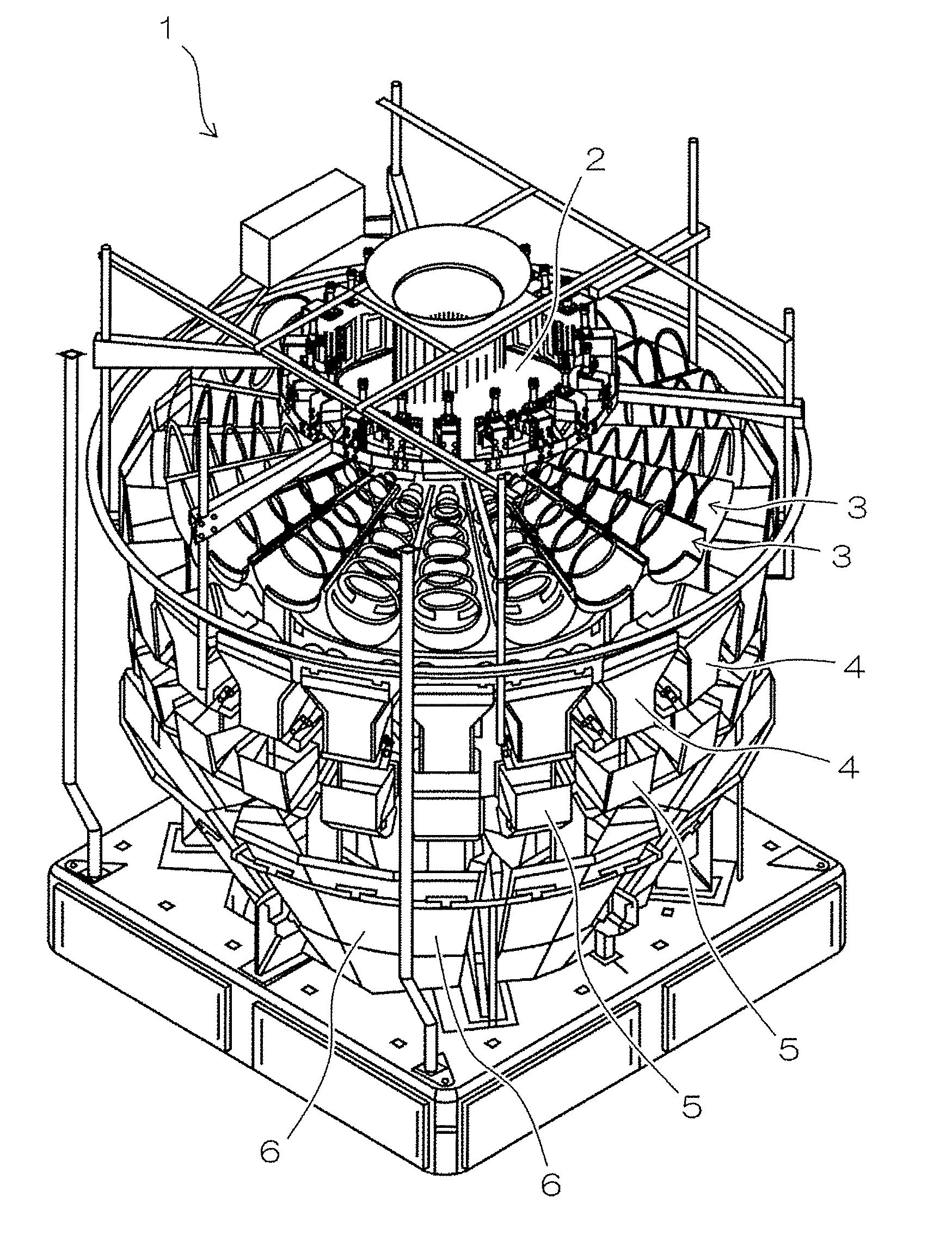
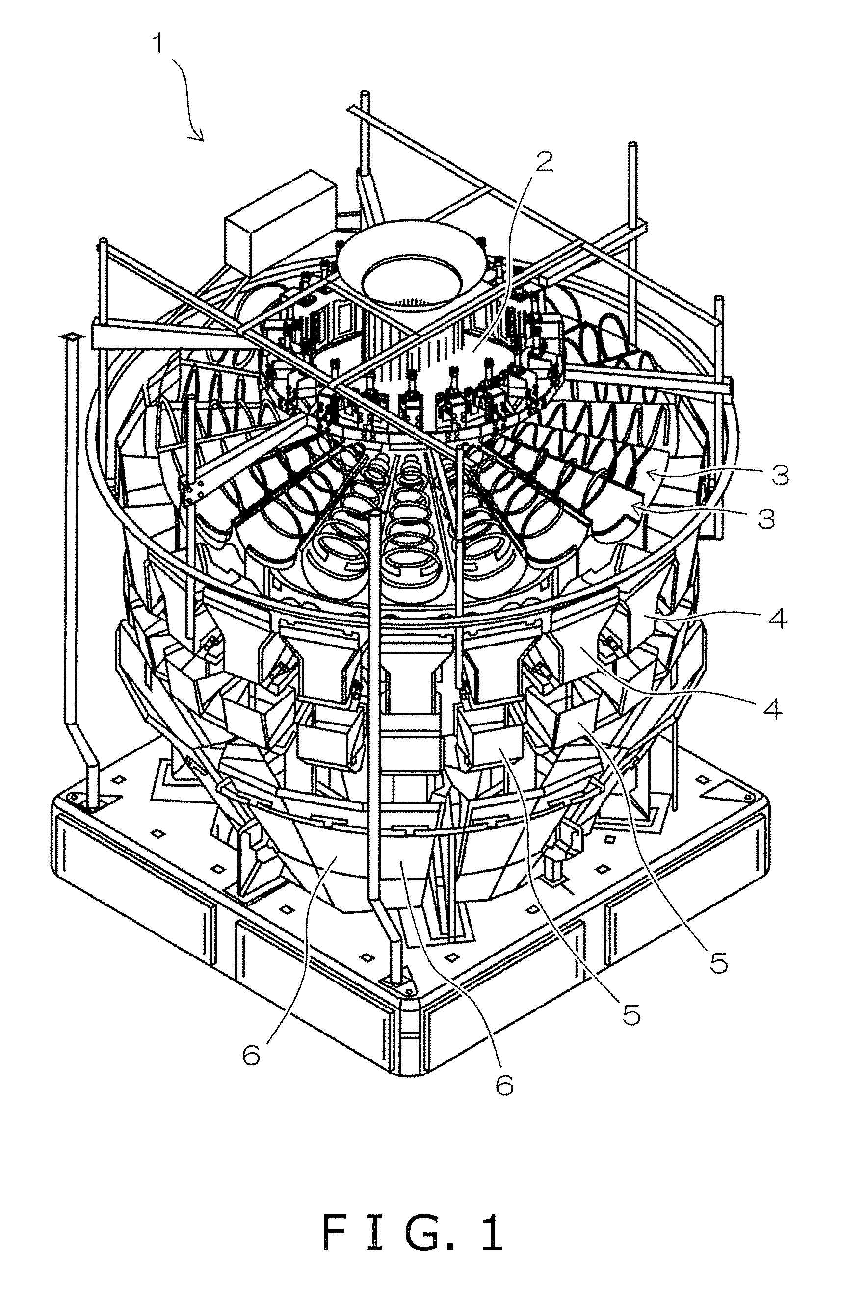
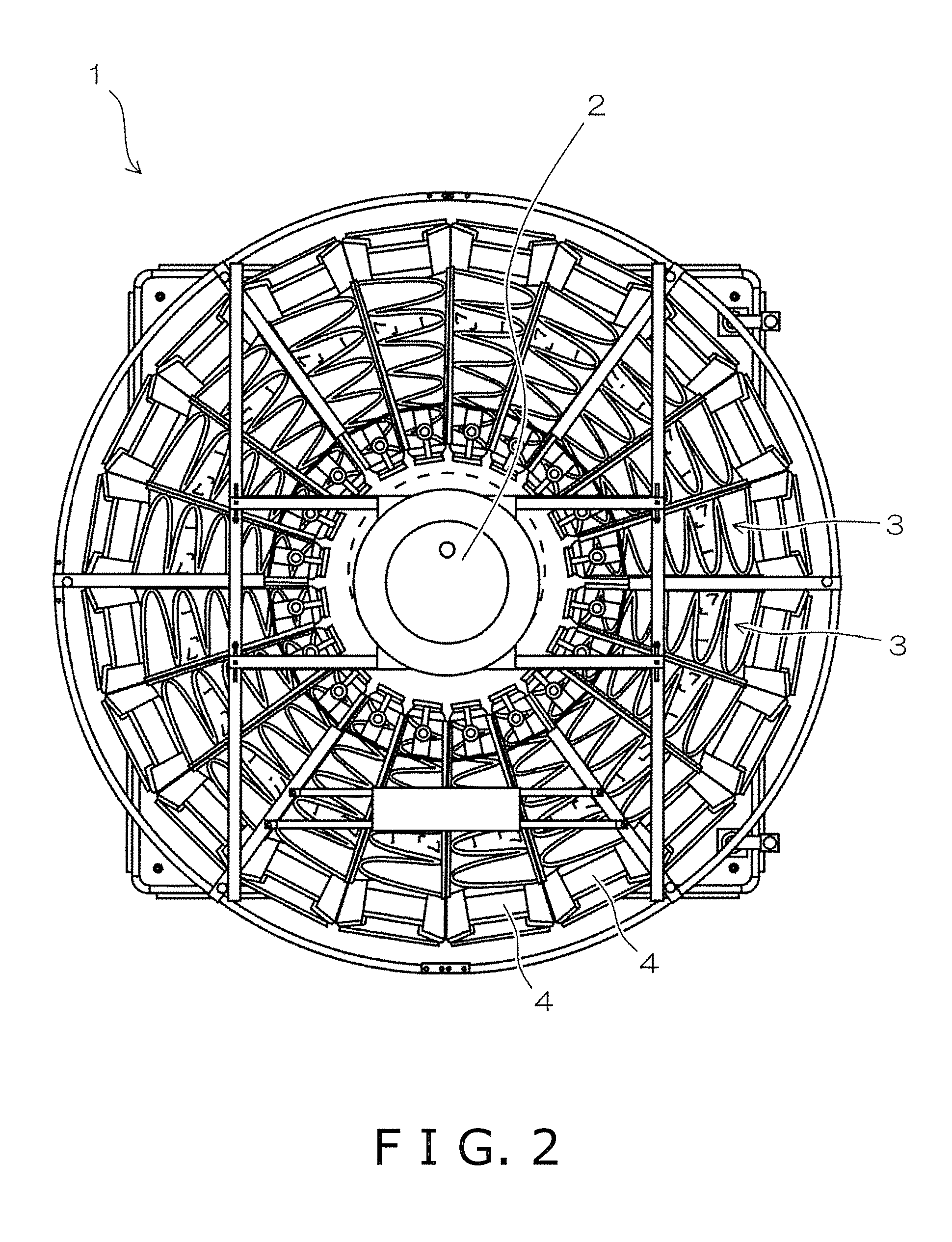
[0034]Referring initially to FIGS. 1 through 7, a combination weighing apparatus 1 is illustrated in accordance with a first embodiment. FIG. 1 is a perspective view showing the overall configuration of the combination weighing apparatus 1. FIG. 2 is a top plan view of the combination weighing apparatus 1 shown in FIG. 1, as seen from above. The combination weighing apparatus 1 includes a dispersion table 2 (dispersion unit), a plurality of conveying mechanisms 3 (conveying units), a plurality of pool hoppers 4 (part of weighing units), a plurality of weighing hoppers 5 (part of weighing units), and collecting chutes 6, as shown in FIGS. 1 and 2.
[0035]The dispersion table 2 is placed in the substantial center of the main body of the combination weighing apparatus 1. The conveying mechanisms 3 are arranged in a generally circular alignment around the periphery of the dispersion table 2. In the present embodiment, the combination weighing apparatus 1 includes twenty conveying mechanis...
second embodiment
[0053]Referring now to FIGS. 8-19, a combination weighing apparatus 101 in accordance with a second embodiment will now be explained. In view of the similarity between the first and second embodiments, the parts of the second embodiment that are identical or equivalent to the parts of the first embodiment will be given the same reference numerals as the parts of the first embodiment. Moreover, the descriptions of the parts of the second embodiment that are identical or equivalent to the parts of the first embodiment may be omitted for the sake of brevity.
[0054]FIG. 8 is a perspective view showing the overall configuration of the combination weighing apparatus 101 according to the second embodiment. The combination weighing apparatus 101 according to the second embodiment differs from the combination weighing apparatus 1 according to the first embodiment mainly in that one or combination of conveying mechanisms 3A to 3C described hereinafter is used instead of the conveying mechanism...
modified examples
[0084](1) FIGS. 20 and 21 are side views showing the structures of conveying mechanisms 3 according to first and second modifications, respectively.
[0085]Referring to FIG. 20, one end of a bent rod-shaped support member 61 is fixed to the outside end 31 of a spiral member 16. The other end of the support member 61 is fixed to a bearing 60. The bearing 60 is rotatably fixed to a specific location on the frame of the combination weighing apparatus 1 or 101, as shown in FIGS. 3 through 5. FIGS. 3 and 4 show an example in which the present modification is applied to only one of two conveying mechanisms 3, but the present modification can be applied to all of a plurality of conveying mechanisms 3.
[0086]Referring to FIG. 21, one end of a rod-shaped support member 51 is fixed to a rotating shaft 12 or 17. The other end of the support member 51 is fixed to a bearing 60. As in the above description, the bearing 60 is rotatably fixed to a specific location on the frame of the combination weig...
PUM
 Abstract
Description
Claims
Application Information