
Ice barrels with stackable configuration

Inactive Publication Date: 2009-11-12
LINDER NATHAN
View PDF4 Cites 3 Cited by
  • Summary
  • Abstract
  • Description
  • Claims
  • Application Information

AI Technical Summary

Benefits of technology

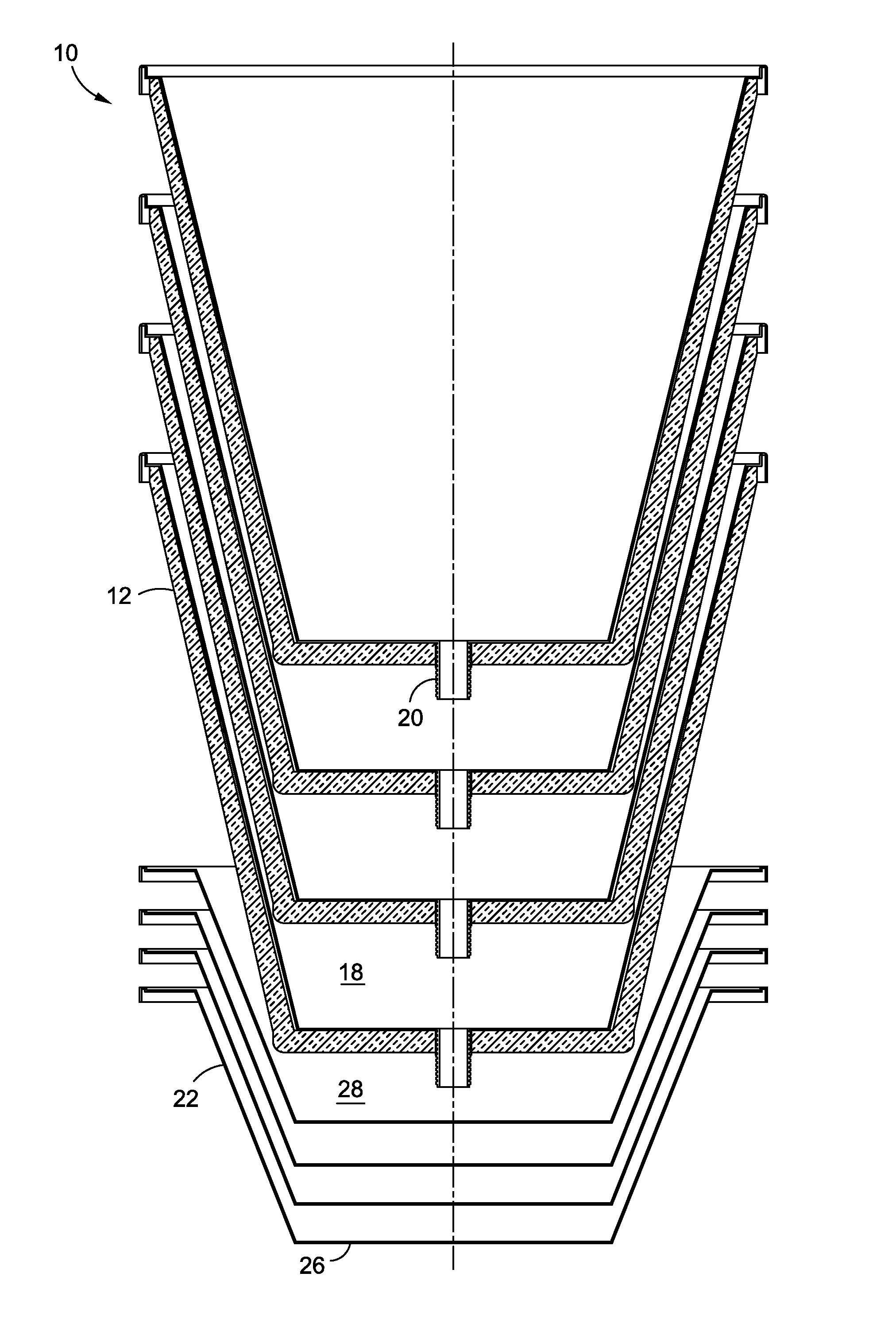
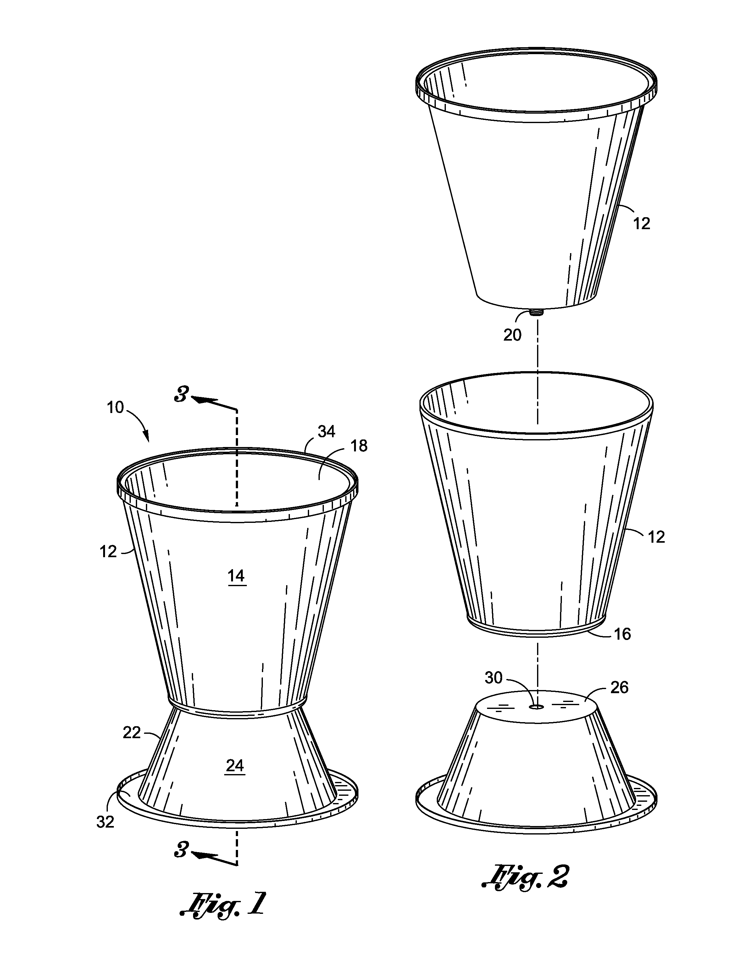
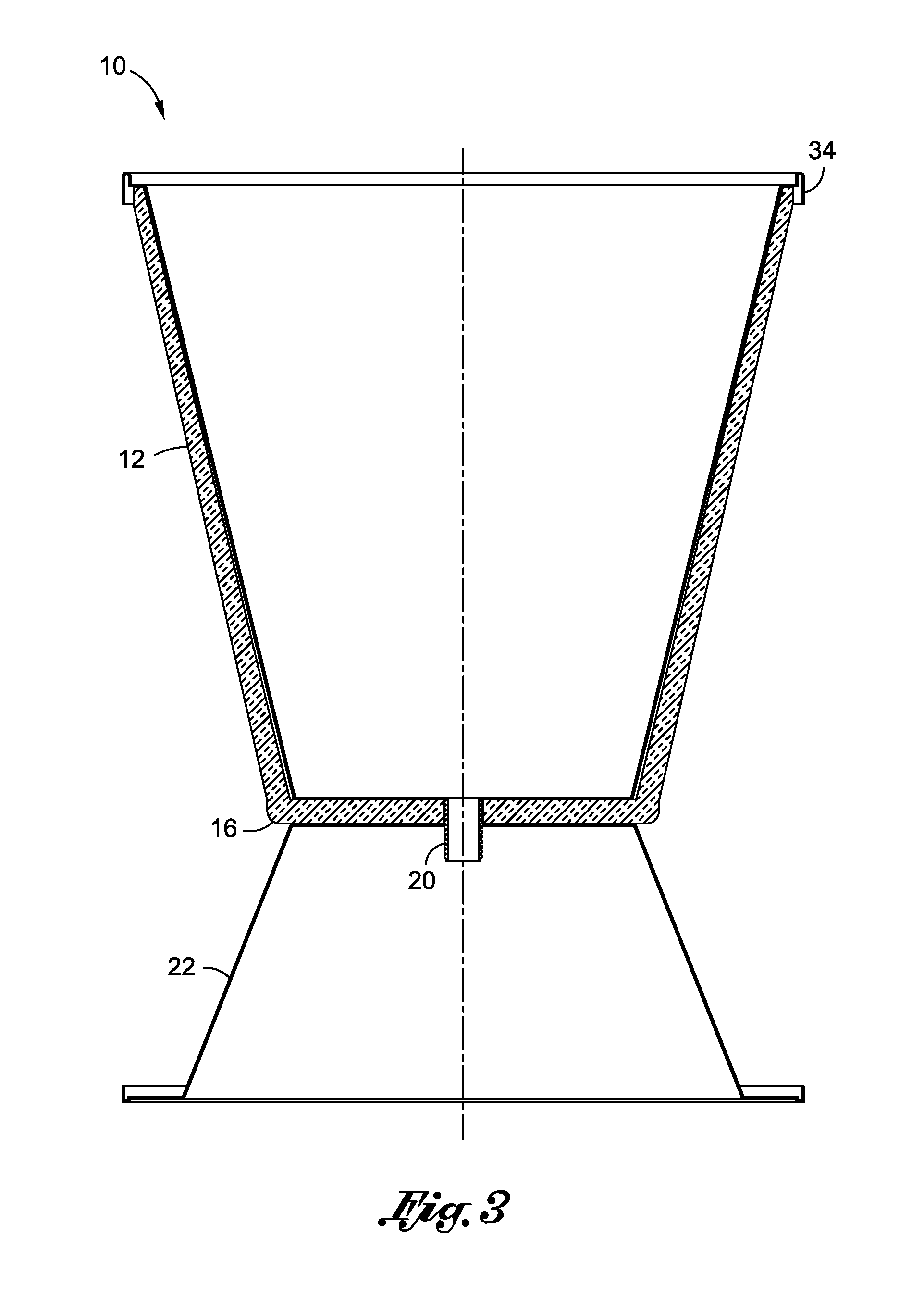
[0010]In yet another embodiment of the present invention, the interior cavity of the receptacle unit is insulated for minimizing heat gain. It is also contemplated that the receptacle unit is coupled to the base unit when the aperture of the top wall of the base unit receives the drain outlet of the receptacle unit. The receptacle unit may also include a peripheral inner flange portion along the edge of the continuous sidewall. Additionally, the base unit of the stackable beverage container may also include a peripheral inner flange portion along the edge of the continuous sidewall.

Problems solved by technology

Further, other beverages containers well know in the art and in the marketplace are not configured for storage saving vertical stacking when the beverage containers are disassembled.
For example, the cylinder beverage container configuration is difficult to stack.
Typically, these stackable beverage containers are very limited to the amount of beverage containers that may be stackable one on top of the other.
Furthermore, these beverage containers are stored in storage containers and trucks and utilize a lot of storage space.
The beverage containers that are stackable are typically very limited to the quantity of beverage containers that are vertically stackable upon one another and therefore do not provide a stackable configuration that is compact and efficient for storage or shipping.
In other words, although the containers may be stackable, the portion of the beverage container that is accepted into another beverage container in a stackable configuration is often limited.
This limitation results in a stackable configuration of a plurality of beverage containers reaching a vertical height that may be insufficient for space saving storage.

Method used


Image

  • Ice barrels with stackable configuration
  • Ice barrels with stackable configuration
  • Ice barrels with stackable configuration

Examples


Embodiment Construction

[0016]The above description is given by way of example, and not limitation. Given the above disclosure, one skilled in the art could devise variations that are within the scope and spirit of the invention disclosed herein, including various ways of stacking beverage containers. Further, the various features of the embodiments disclosed herein can be used alone, or in varying combinations with each other and are not intended to be limited to the specific combination described herein. Thus, the scope of the claims is not to be limited by the illustrated embodiments.

[0017]Referring now to FIG. 1, the stackable beverage container 10 is adapted for holding ice and beverages within a receptacle unit 12. The receptacle unit 12 of the stackable beverage container 10 includes an open top for receiving ice and beverages. The ice and beverages are also withdrawn from the receptacle unit 12 of the stackable beverage container 10 via the open top. In one embodiment, the stackable beverage contai...


PUM


Abstract

A stackable beverage container adapted to hold ice and beverages. The stackable beverage container includes a receptacle unit. The receptacle unit includes a continuous sidewall coupled to a bottom wall. The continuous sidewall and the bottom wall of the receptacle unit form a receptacle interior cavity. The receptacle interior cavity is the portion of the stackable beverage container used to hold or store ice and beverages placed therein. The bottom wall of the receptacle unit also includes a drain outlet formed therein. Additionally, the stackable beverage container includes a base unit. The base unit includes a continuous sidewall coupled to a top wall. The continuous sidewall and the top wall of the base unit form a base interior cavity. The top wall of the base unit includes an aperture formed therein. The aperture may receive the drain outlet of the receptacle unit. The bottom wall of the receptacle unit is also detachably coupled to the top wall of the base unit.

Description

CROSS-REFERENCE TO RELATED APPLICATIONS[0001]Not ApplicableSTATEMENT RE: FEDERALLY SPONSORED RESEARCH / DEVELOPMENT[0002]Not ApplicableBACKGROUND[0003]The present invention relates generally to ice barrels adapted for holding ice and beverages and, more particularly, to ice barrels with a stackable configuration for stacking vertically.[0004]Ice barrel containers or “beverage containers” are well-known in the art and are extensively utilized at retail markets, sporting events, and promotional events. The beverage containers facilitate the storage of ice and beverages. Ice is placed within an interior cavity of the ice barrel. Beverages may then be dispersed within the ice barrel. The ice within the barrel keeps the beverages placed therein cool. Beverages, e.g., soft drinks or beer in cans or bottles, are often displayed at retail outlets in chilled containers such as ice barrels. The ice barrels are frequently located close to check-out counters to entice impulse purchases by departi...

Claims


Application Information

Patent Timeline
IPC IPC(8): B65D21/02
CPCB65D11/02B65D25/24B65D25/16B65D21/0234
Inventor LINDER, NATHAN
Owner LINDER NATHAN
Learn More