Engine cooling

Inactive Publication Date: 2008-12-25
ROLLS ROYCE PLC
View PDF28 Cites 2 Cited by
  • Summary
  • Abstract
  • Description
  • Claims
  • Application Information

AI Technical Summary

Benefits of technology

[0004]Accordingly the present invention provides an engine for an aircraft, the engine comprising an engine nacelle including an inner surface and an outer surface, at least one cavity defined between the inner surface and the outer surface, the nacelle including heat transfer means comprising an evaporatable liquid within the at least one cavity, a component or part

Problems solved by technology

It will be understood with regard to aircraft in particular, there are limitations upon the available heat exchanger area due to weight and volume accommodation problems.
However, in a second cooling scenario when the engine i

Method used


Image

  • Engine cooling
  • Engine cooling
  • Engine cooling

Examples


Embodiment Construction

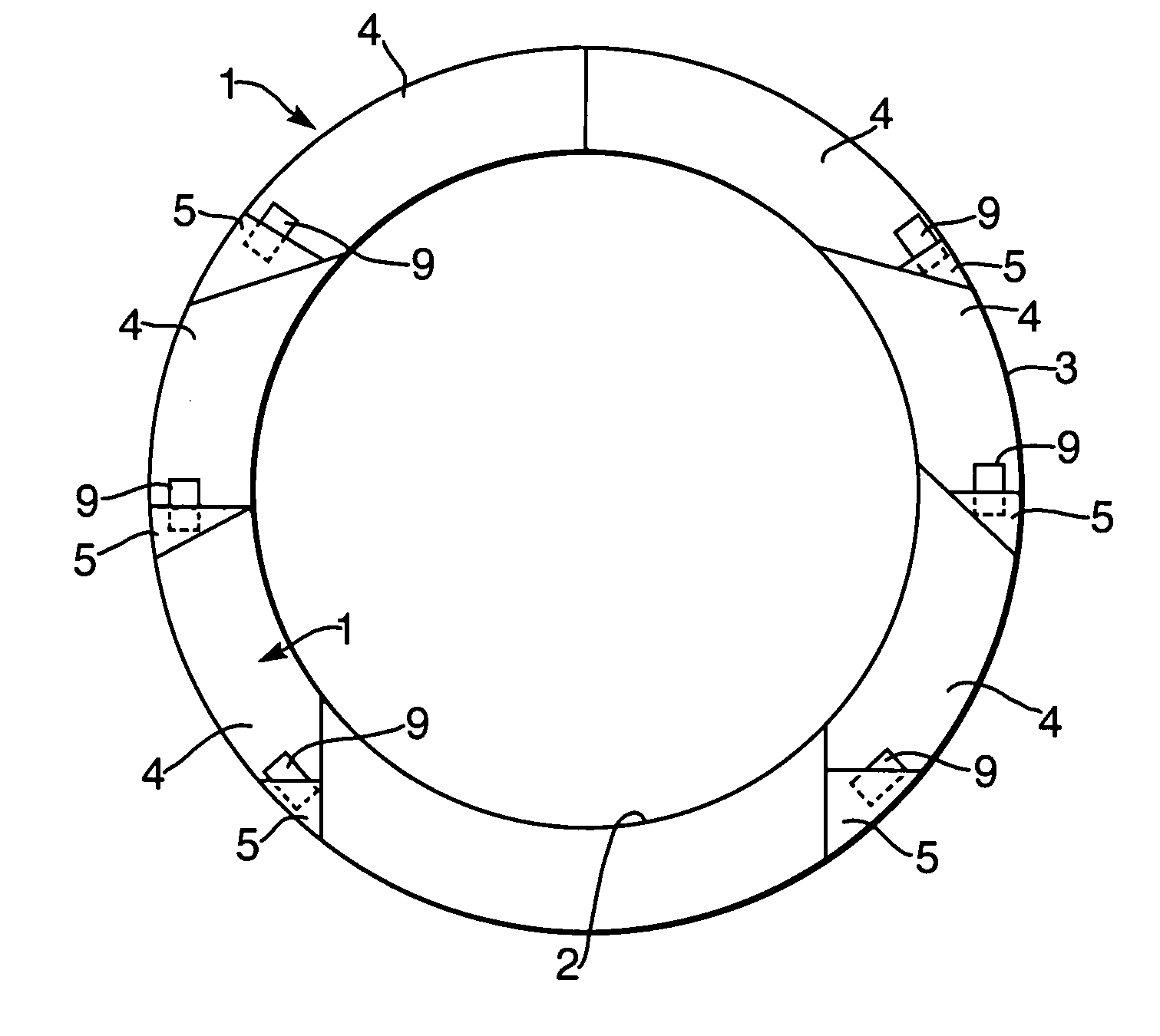
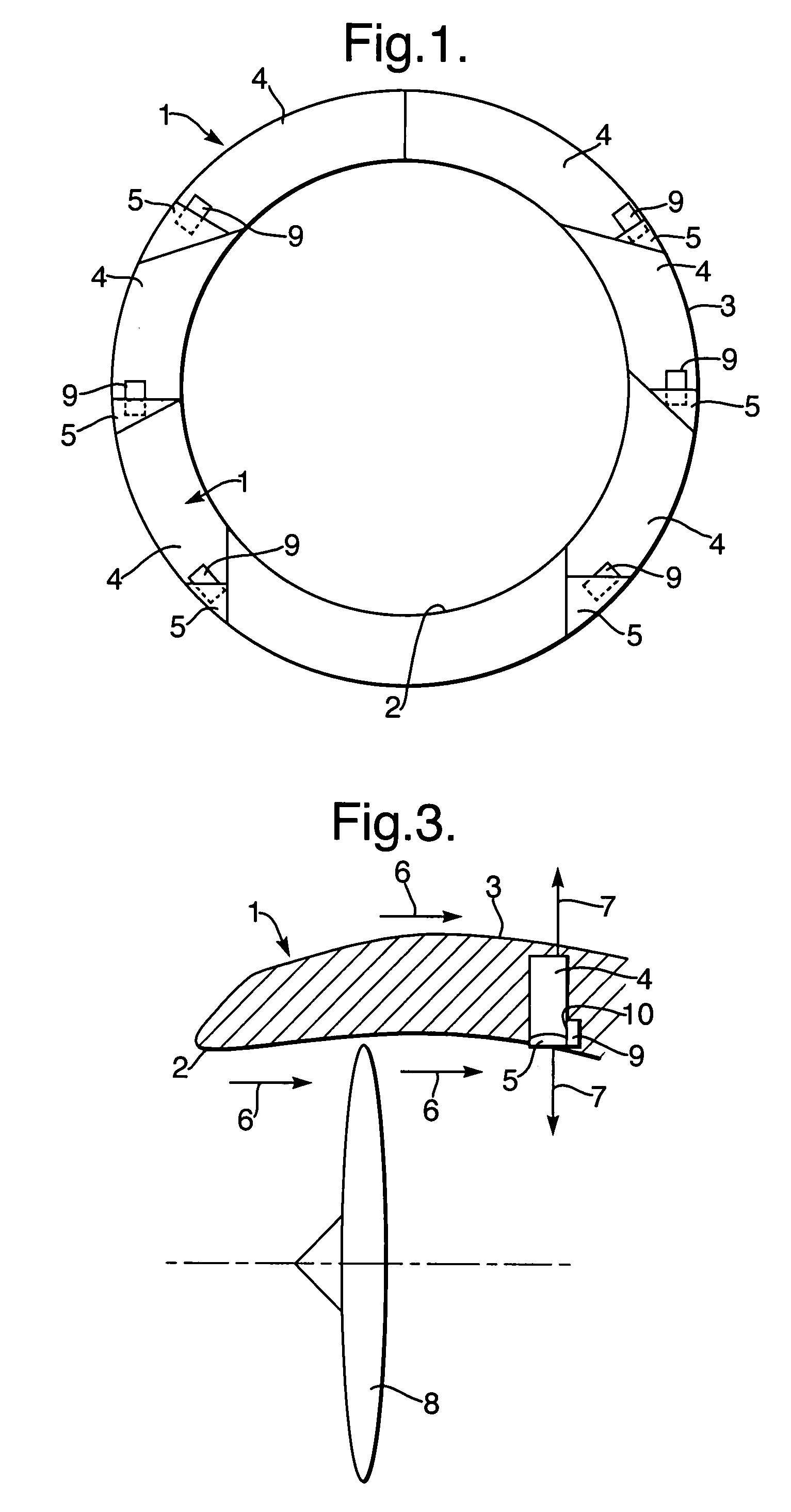
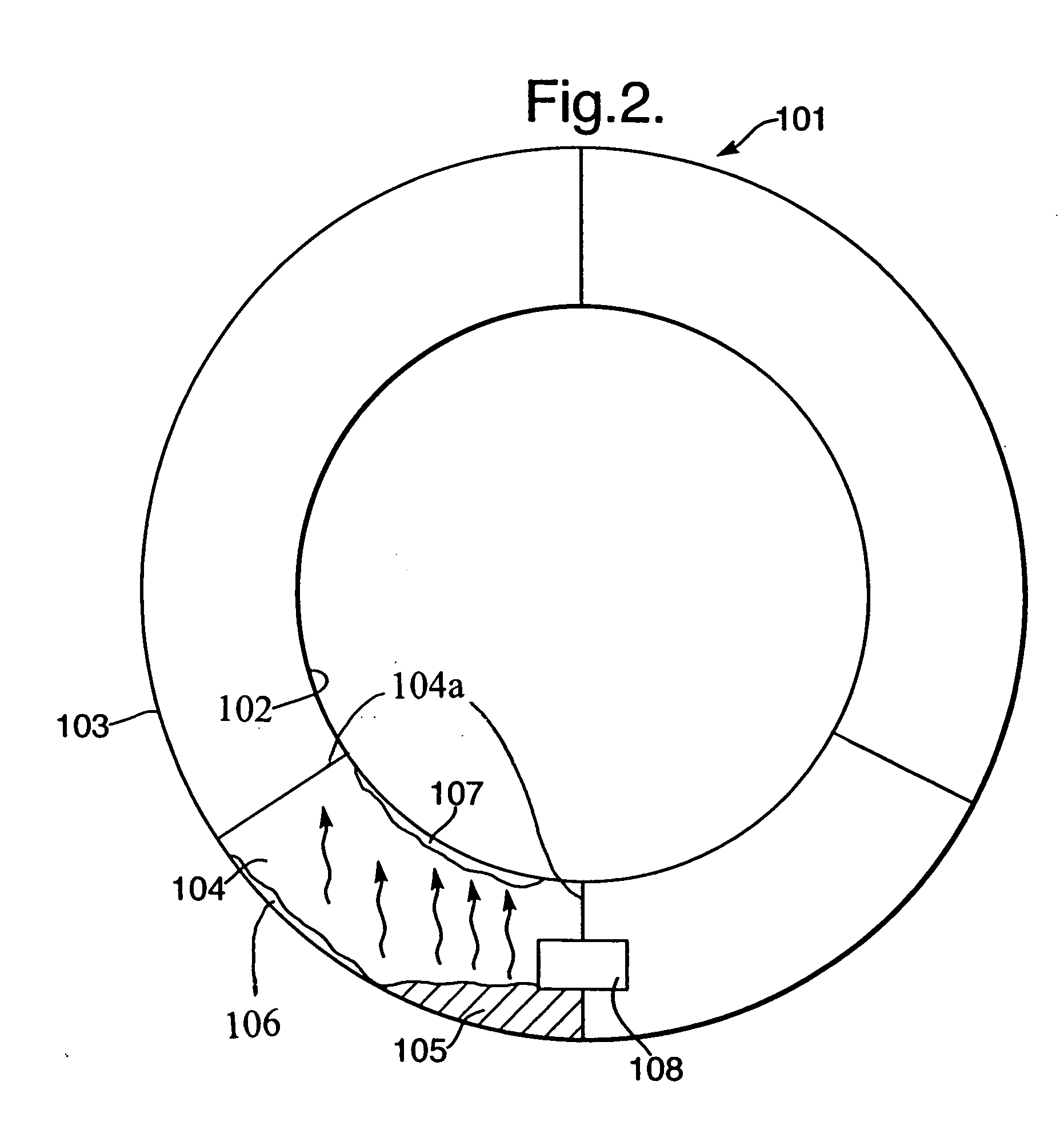
[0016]As indicated above, whilst an engine is idling prior to takeoff, there is generally limited cooling airflow and a generally higher ambient ground temperature than at altitude. Nevertheless, there still remains some airflow through a bypass duct generated by the fan of the engine. This airflow is at ground ambient temperature. The present invention utilises a heat transfer process by which an evaporatable liquid is utilised to transfer heat losses from electronic or other devices to a colder surface. A colder surface in this case is either the bypass duct interface or the outer nacelle surface. The gas will condense on the colder surface available (thereby passively switching between available surfaces) and the newly formed liquid will be available for further heat pick up from the heat source, component or part. Additionally, it will be appreciated that an intermediate fuel or other heat exchanger could be used in order to further condense the evaporatable liquid. During flyin...


PUM


Abstract

Cavities 4 are defined within an engine nacelle 1 with an inner surface 2 and an outer surface 3. Within these cavities 4, an evaporatable liquid 5 is arranged such that a proportion of the liquid 5 is in a gaseous phase in order to facilitate heat transfer between the inner surface 2 or the outer surface 3 and a hot surface. The liquid condenses upon the inner surface 2 or the outer surface 3 and collects into a pool for subsequent further evaporation by the hot surface of an insulated gate bi-polar transistor or convertor/generator components in order to facilitate further cooling of electric components housed or arranged in the nacelle 1 or nearby.

Description

[0001]This is a Continuation-In-Part of National application Ser. No. 10 / 962,449 filed Oct. 13, 2004 and currently pending. The present invention relates to engine cooling and more particularly to engine component cooling in aircraft during idle modes prior to takeoff.FIELD OF THE INVENTION Background of the Invention[0002]It will be appreciated that engines, and in particular, aircraft engine components, such as electrical or electronic devices and / or static structural parts, must be cooled in order to remain within acceptable operational temperature ranges etc. Cooling with regard to aircraft engines can be achieved through utilisation of ambient airflow bypass through the engine utilising a heat exchanger and the differential between the cooler bypass side and the hot engine side of the exchanger. Bypass ambient air cooling is conventionally used for cooling an engine when the temperature differential and available heat exchanger area are adequate. It will be understood with rega...

Claims


Application Information

Patent Timeline
IPC IPC(8): F02K11/00F02K99/00
CPCB64D29/00F02C7/16Y02T50/675F05D2260/208F05D2260/209Y02T50/60
Inventor SIEBERT, ANNEGRET W.
Owner ROLLS ROYCE PLC
Why Eureka
Try Eureka