Air over air refrigeration system

Active Publication Date: 2019-08-13
KWICK COOL INC
View PDF10 Cites 1 Cited by
  • Summary
  • Abstract
  • Description
  • Claims
  • Application Information

AI Technical Summary

Benefits of technology

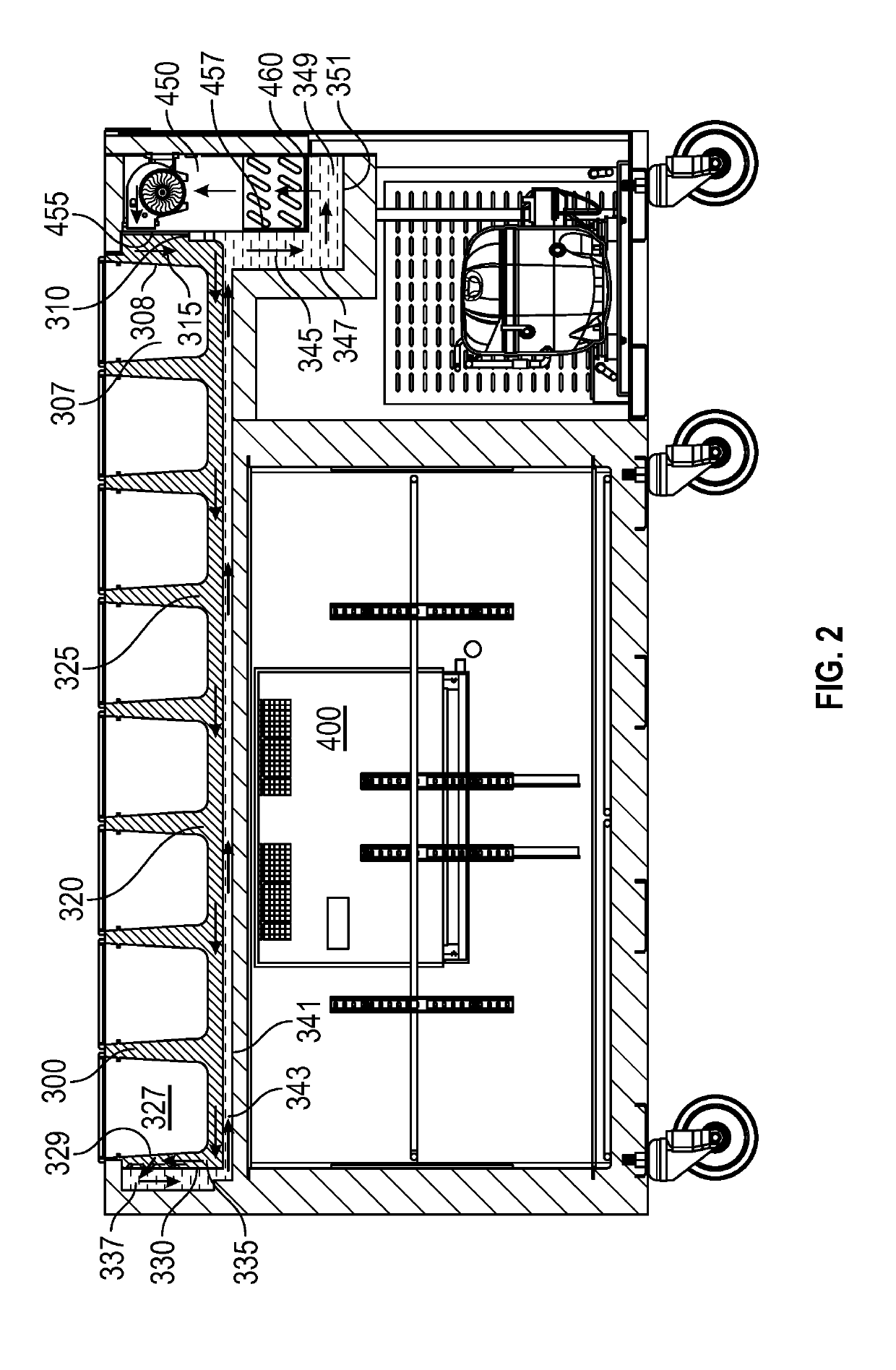
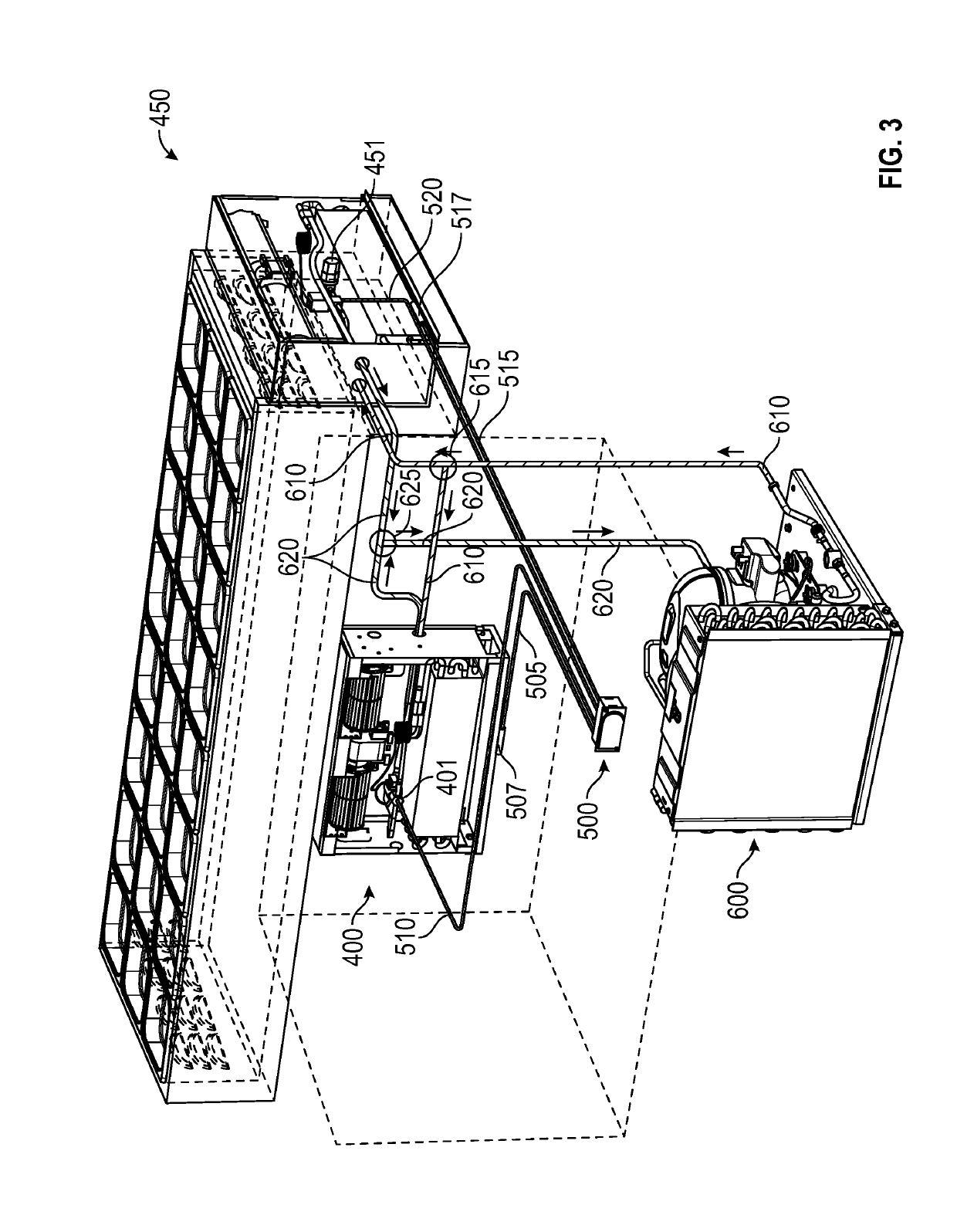
[0010]The presently disclosed embodiments provide new innovations by the artful placement of evaporator coil components or Turbo Coil™ evaporator coil/blower systems to facilitate the disclosed upper air flow distribution system for a preparation table application and by the artful placement of evaporator coil components to facilitate cooling in the lower refrigeration zone. The two placements or positions of the evaporator coil components not only enable new air flow distribution systems by also enable efficient accessing and servicing of the evaporator coil components.
[0011]For example, for the upper cooling system, the evaporator coil components or patented Turbo Coil system is placed at an end of the prep table, such that the evaporator coil components are easily accessible at the edge of the table and such that the upper section of the evaporator coil system blows cooled air in a first cool air channel of the prep table and such that the lower section of the evaporator coil system accepts return air as a result of the artful integration of the evaporator coil system and the design of the prep table airflow system. The presently disclosed embodiments leverage the native design of the evaporator coil system and blower system to efficiently supply cooled air to the cool air intake channel of the prep table while efficiently accepting the warmed return air at the lower portion of the evaporator coil system. The artful design of the disclosed prep table airflow system allows for a seamless integration with the upper evaporator coil/blower

Problems solved by technology

Such systems often use one condensing unit and one evaporation unit, resulting in an overuse of refrigeratio

Method used


Image

  • Air over air refrigeration system
  • Air over air refrigeration system
  • Air over air refrigeration system

Examples


Example

REFERENCE NUMERALS IN THE DRAWINGS

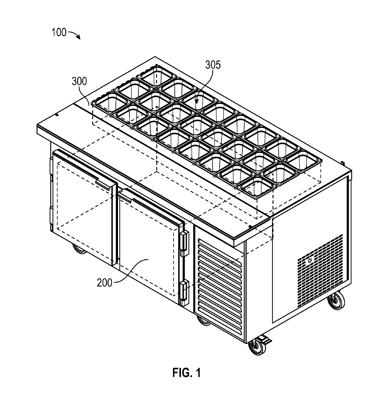
[0026]100 food preparation or serving table in general[0027]200 lower refrigeration compartment or lower cooling zone[0028]300 upper refrigeration compartment or upper cooling zone[0029]305 removable food pans or food containers[0030]307 proximal food container[0031]308 proximal vertical lateral wall of a proximal food container[0032]310 proximal vertical wall of upper refrigeration compartment 300[0033]315 proximal vertical cooling channel or void of upper refrigeration system 300[0034]320 horizontal barrier or wall within lower portion of the upper refrigeration compartment 300[0035]325 lower horizontal channel for cooled air within the upper refrigeration compartment 300[0036]327 distal food container[0037]329 lateral vertical wall of distal food container 327[0038]330 distal vertical wall within upper refrigeration compartment 300[0039]335 distal vertical channel within upper refrigeration compartment 300[0040]337 distal vertical return channel[...


PUM


Abstract

A food prep table may include an upper chilling zone and a lower chilling zone, with each chilling zone containing an evaporation coil system, such as a TurboCoil™ system. The two evaporation coil systems are monitored and controlled by a dual thermostat and control unit (500) having temperature sensor probes in each chilling zone and controlling solenoid valves within each evaporation coil system. By the artful use and implementation of the dual thermostat and control unit, and by the artful use of T junctures in refrigerant supply and return lines, the disclosed embodiments enable a single condensing unit (600) to service both evaporation coil systems to achieve new efficiencies in the cost, refrigeration capacity, and thermal and mechanic attributes of the system. Moreover, an efficient dual air over air flow assembly is disclosed wherein chilled air is moved within the upper chilling zone in a manner that leverages the native configuration and cabinet surface areas of the evaporation coil systems.

Description

CROSS-REFERENCE TO RELATED APPLICATIONS[0001]This is a non-provisional utility application based upon and claiming the priority of provisional application 62 / 307,741 filed on Mar. 14, 2016. This related patent application is incorporated herein by reference and made a part of this application. If any conflict arises between the disclosure of the invention in this utility application and that in the related application(s), the disclosure in this utility application shall govern. Moreover, the inventor(s) incorporate herein by reference any and all patents, patent applications, and other documents hard copy or electronic, cited or referred to in this application or the related application(s).COPYRIGHT AND TRADEMARK NOTICE[0002]This application includes material which is subject or may be subject to copyright and / or trademark protection. The copyright and trademark owner(s) has no objection to the facsimile reproduction by any of the patent disclosure, as it appears in the Patent and T...

Claims


Application Information

Patent Timeline
IPC IPC(8): F25D31/00F25D11/02A47F3/04A47B31/02A47F10/06F25B5/02F25D17/06
CPCF25D31/00A47B31/02A47F3/04A47F10/06F25B5/02A47F3/0413A47F3/0452
Inventor DELGADILLO, HECTOR
Owner KWICK COOL INC
Why Eureka
Try Eureka