Image forming apparatus, optical scanning device, and plastic lens

Inactive Publication Date: 2009-07-02
RICOH KK
View PDF5 Cites 4 Cited by
  • Summary
  • Abstract
  • Description
  • Claims
  • Application Information

AI Technical Summary

Benefits of technology

[0013]This patent specification describes a plastic lens. In one example, a plastic lens is molded in a mold for molding a plastic lens. The mold for molding a plastic lens includes a pair of first molding blocks and a pair of second molding blocks. The first molding blocks transfer light incidence and emission surfaces. The second molding blocks are provided to both ends of the first molding blocks, disposed parallel to an optical axis and facing each other, and transfer non-light-passing surfaces. At least one of the second molding blocks includes an elongated slit-like ventilation hole having a length of a light effective range or longer and extending in a main scanning direction of the light incidence and emission surfaces along positions equidistant from the light incidence and emission surfaces. Through the ventilation hole, air is sprayed onto molten resin in a process of resin cooling and solidification to facilitate cooling of the resin.
[0014]This patent specification further describes an optical scanning device. In one example, an optical scanning device includes a plastic lens molded in a mold for molding a plastic lens. The mold for molding a plastic lens includes a pair of first molding blocks and a pair of second molding blocks. The first molding blocks transfer light incidence and emission surfaces. The second molding blocks are provided to both ends of the first molding blocks, disposed parallel to an optical axis a

Problems solved by technology

If the pressure of the molten resin in the cavity is reduced, however, the resin contracts in the subsequent cooling and solidification process.
Further, in the molding of a thick optical device which is uneven in thickness, the cooling speed of the resin is naturally different from site to site.
The difference results in a difference in the contraction amount of the resin.
As a result, such phenomena as deterioration of the shape accuracy and internal strain occur.
Further,

Method used


Image

  • Image forming apparatus, optical scanning device, and plastic lens
  • Image forming apparatus, optical scanning device, and plastic lens
  • Image forming apparatus, optical scanning device, and plastic lens

Examples


Example

[0037]In describing the embodiments illustrated in the drawings, specific terminology is employed for the purpose of clarity. However, the disclosure of this patent specification is not intended to be limited to the specific terminology so used, and it is to be understood that substitutions for each specific element can include any technical equivalents that operate in a similar manner.

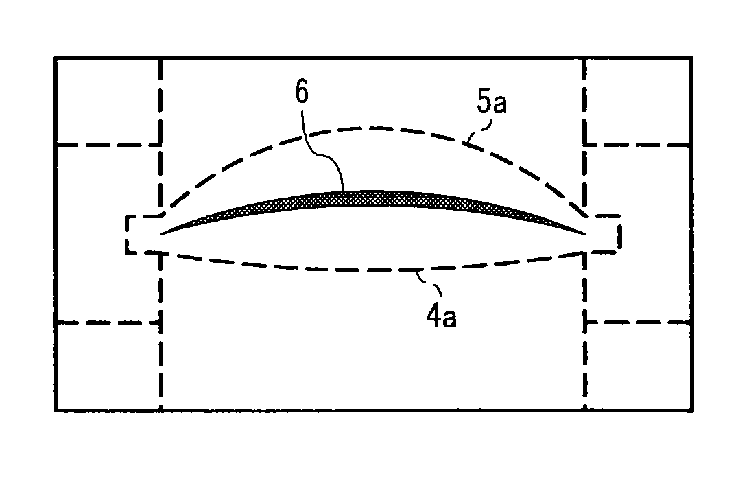
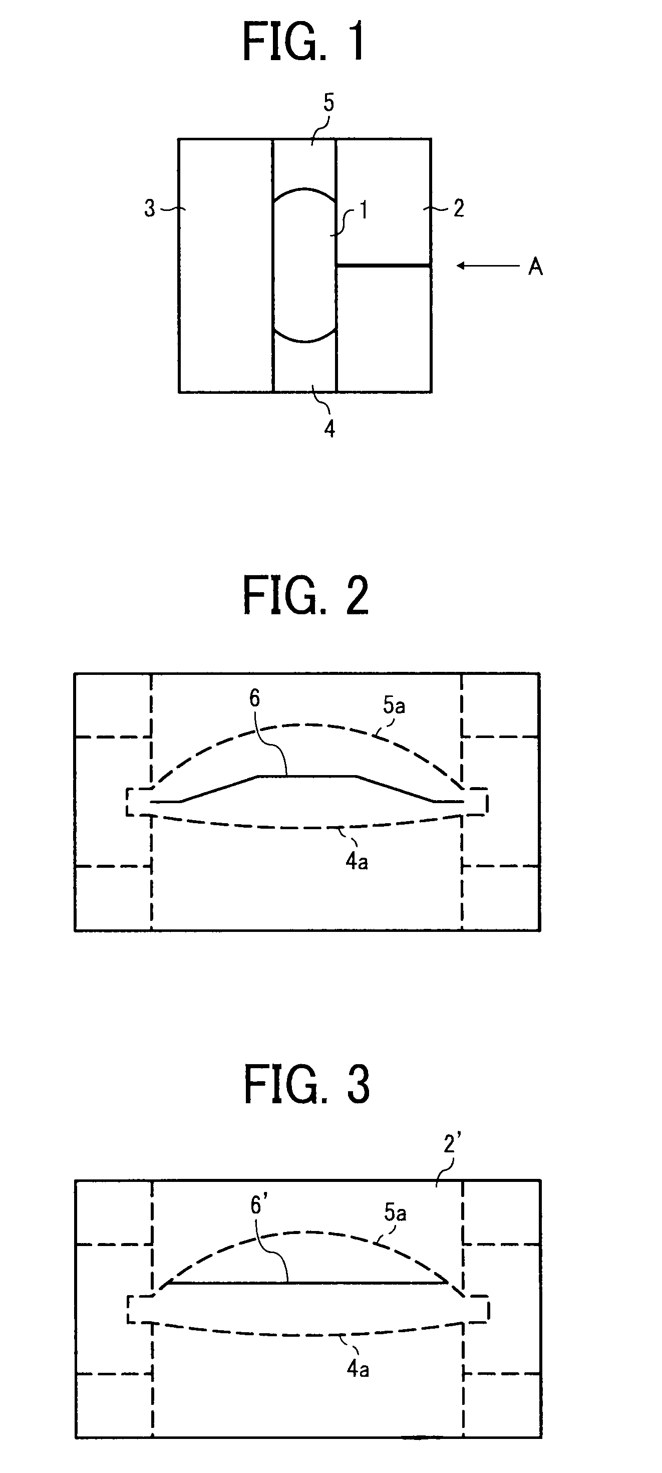
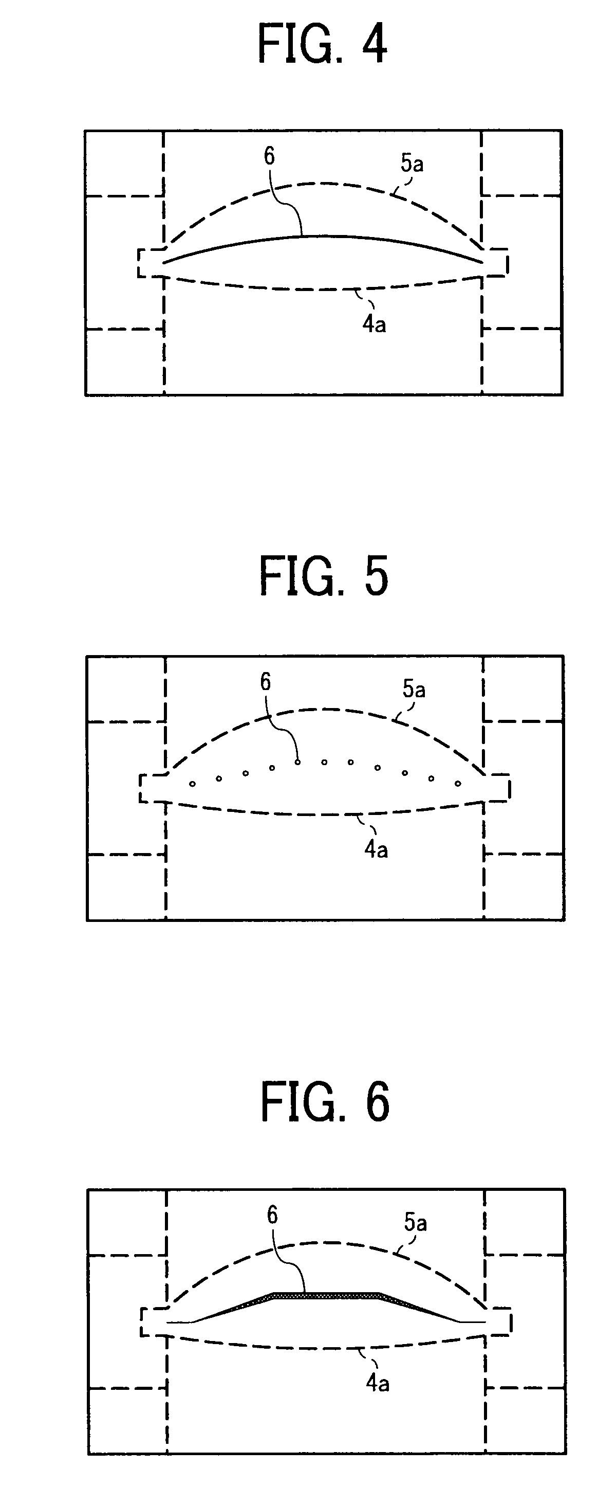
[0038]Referring now to the drawings, wherein like reference numerals designate identical or corresponding parts throughout the several views, a mold for molding a plastic lens according to an embodiment of the present invention will be described.

[0039]The mold for molding a plastic lens includes a pair of first molding blocks and a pair of second molding blocks. The first molding blocks are configured to transfer a light incidence surface and a light emission surface, respectively. The second molding blocks are provided to both end portions of the first molding blocks to be parallel to a light beam di...


PUM

PropertyMeasurementUnit
Timeaaaaaaaaaa
Lengthaaaaaaaaaa
Lightaaaaaaaaaa

Abstract

A plastic lens molded in a mold having two first molding blocks and two second molding blocks. The first molding blocks transfer light incidence and emission surfaces. The second molding blocks are provided to both ends of the first molding blocks, disposed parallel to an optical axis and facing each other, and transfer non-light-passing surfaces. At least one of the second molding blocks includes an elongated slit-like ventilation hole having a length of a light effective range or longer and extending in a main scanning direction of the light incidence and emission surfaces along positions equidistant from the light incidence and emission surfaces. Through the ventilation hole, air is sprayed onto molten resin in a process of resin cooling and solidification to facilitate cooling of the resin.

Description

CROSS-REFERENCE TO RELATED APPLICATION[0001]This application claims priority to Japanese Patent Application No. 2007-339700, filed on Dec. 28, 2007, the entire contents of which are hereby incorporated by reference herein.BACKGROUND OF THE INVENTION[0002]1. Field of the Invention[0003]The present invention relates to an image forming apparatus, such as a color digital copier, a multifunction printer (MFP), a laser printer, a facsimile machine, a plotter, and a multifunctional machine combining the functions of these apparatuses, an optical scanning device, and a plastic lens incorporated in the image forming apparatus and the optical scanning device.[0004]2. Discussion of the Background Art[0005]An existing optical writing unit installed in a laser-type digital copier, printer, facsimile machine, or the like includes, as a main component thereof, a rectangular optical device (e.g., a lens and a mirror) having a function of forming an image from laser light and correcting the formed ...

Claims


Application Information

Patent Timeline
IPC IPC(8): G02B3/00B28B1/00
CPCB29C33/046B29L2011/0016B29C45/7337
Inventor TAKAHASHI, GOHAYASHI, EIICHIAOKI, KANIWAMATSU, AKIHIRO
Owner RICOH KK
Why Eureka
Try Eureka