Direct cooling pallet tray for temperature stability for deep ion mill etch process

Inactive Publication Date: 2006-06-08
WODEN TECH INC
View PDF20 Cites 0 Cited by
  • Summary
  • Abstract
  • Description
  • Claims
  • Application Information

AI Technical Summary

Benefits of technology

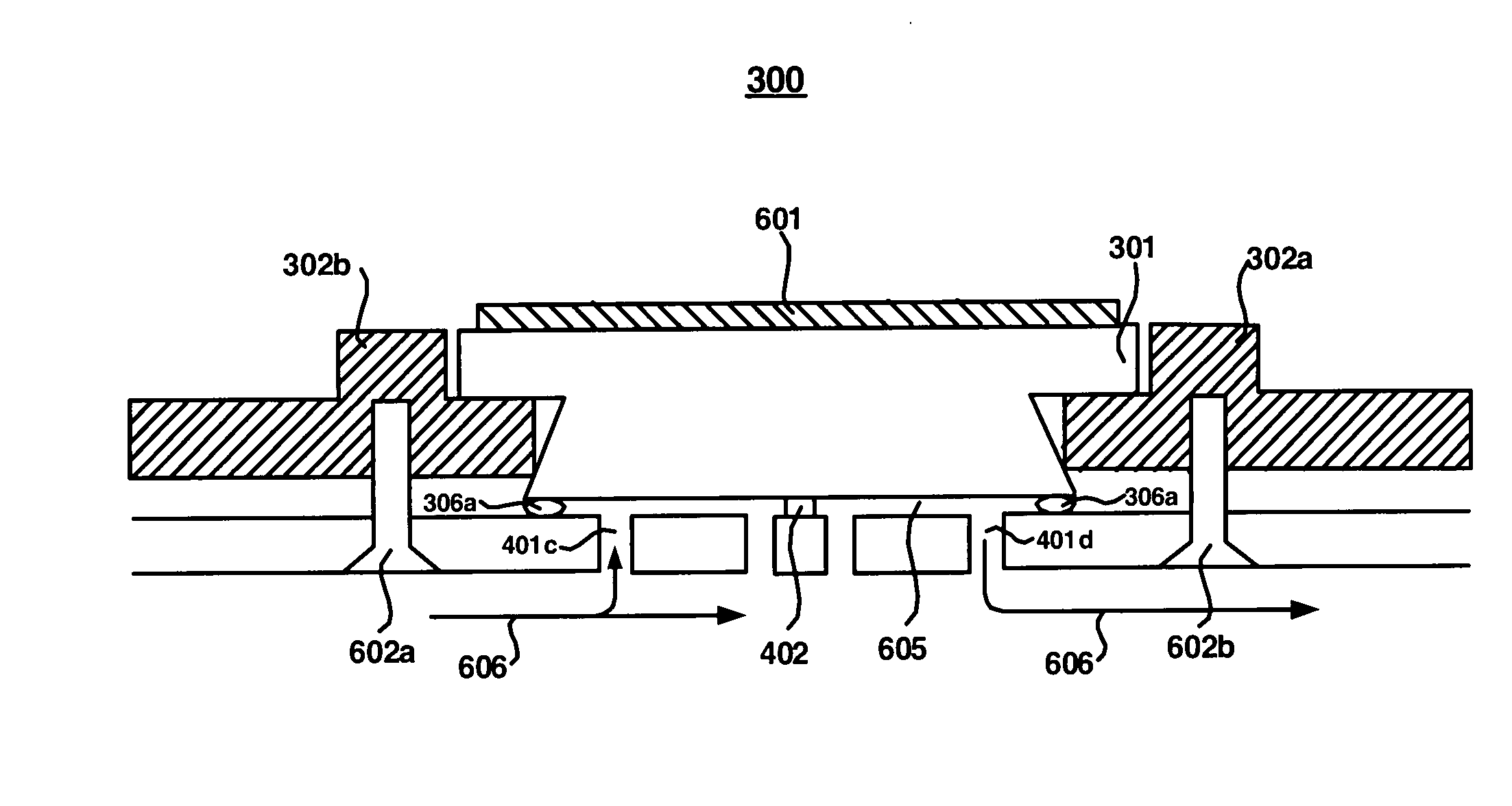
[0005] Embodiments of the present invention are directed to a pallet assembly which facilitates direct cooling of the wafer carrier. In one embodiment, the pallet assembly comprises a frame which holds at least one carrier of a component. The pallet assembly further comprises a tray which is operable for being mechanically coupled with the frame. The tray comprises at least one discreet region which corresponds with the carrier when the tray is coupled with the frame. In embodiments of the pre

Problems solved by technology

However, when performing a deeper etch (e.g., approximately 1.32μ using an ion milling process) current pallet designs cannot dissipate the heat quickly en

Method used


Image

  • Direct cooling pallet tray for temperature stability for deep ion mill etch process
  • Direct cooling pallet tray for temperature stability for deep ion mill etch process
  • Direct cooling pallet tray for temperature stability for deep ion mill etch process

Examples


Example

[0015] Reference will now be made in detail to embodiments of the present invention, examples of which are illustrated in the accompanying drawings. While the present invention will be described in conjunction with the following embodiments, it will be understood that they are not intended to limit the present invention to these embodiments alone. On the contrary, the present invention is intended to cover alternatives, modifications, and equivalents which may be included within the spirit and scope of the present invention as defined by the appended claims. Furthermore, in the following detailed description of the present invention, numerous specific details are set forth in order to provide a thorough understanding of the present invention. However, embodiments of the present invention may be practiced without these specific details. In other instances, well-known methods, procedures, components, and circuits have not been described in detail so as not to unnecessarily obscure asp...


PUM


Abstract

Embodiments of the present invention are directed to a pallet assembly which facilitates direct cooling of the wafer carrier. In one embodiment, the pallet assembly comprises a frame which holds at least one carrier of a component. The pallet assembly further comprises a tray which is operable for being mechanically coupled with the frame. The tray comprises at least one discreet region which corresponds with the carrier when the tray is coupled with the frame. In embodiments of the present invention, the discreet region comprises at least one hole extending through the tray for permitting a coolant medium to dissipate heat from the carrier.

Description

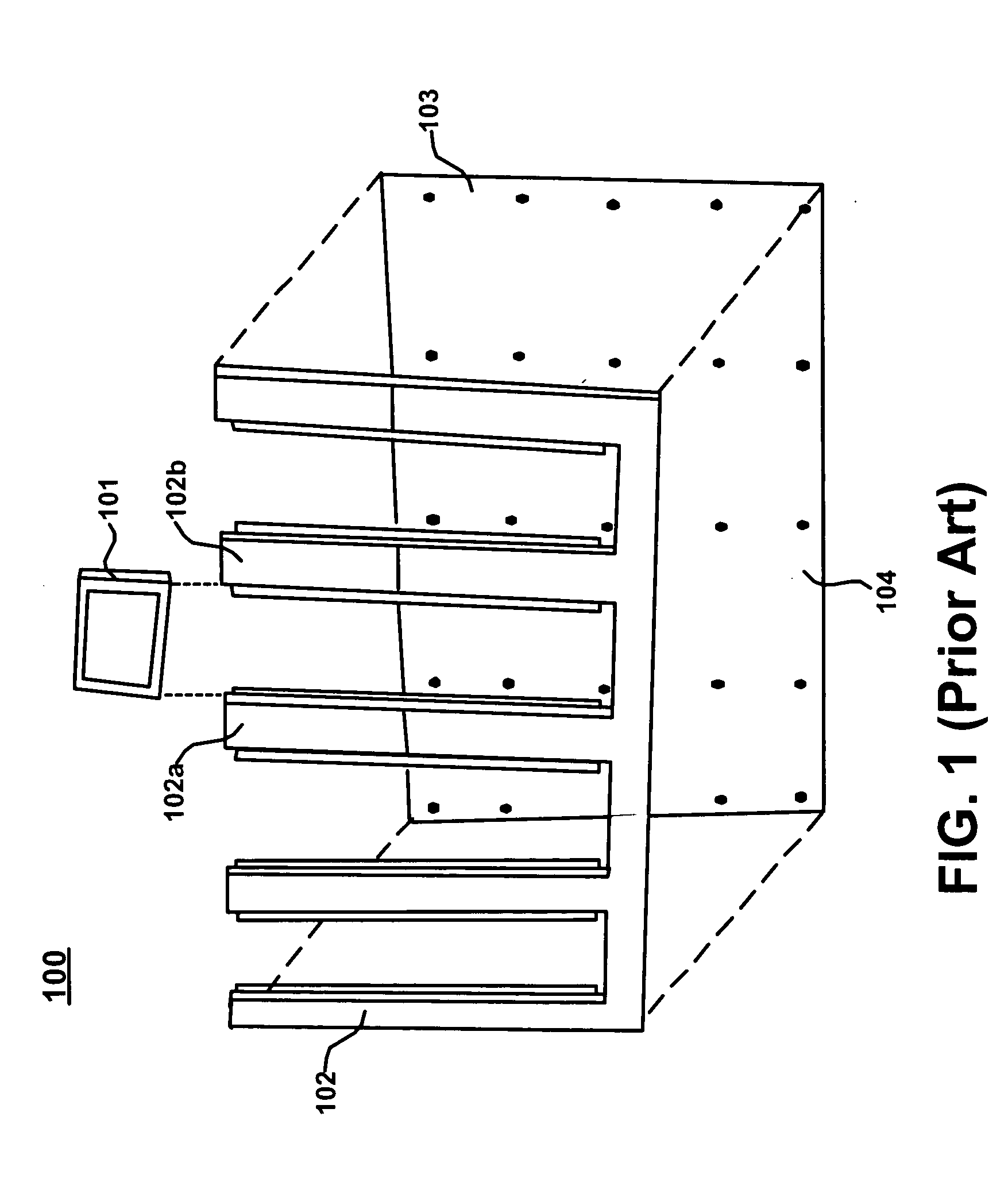
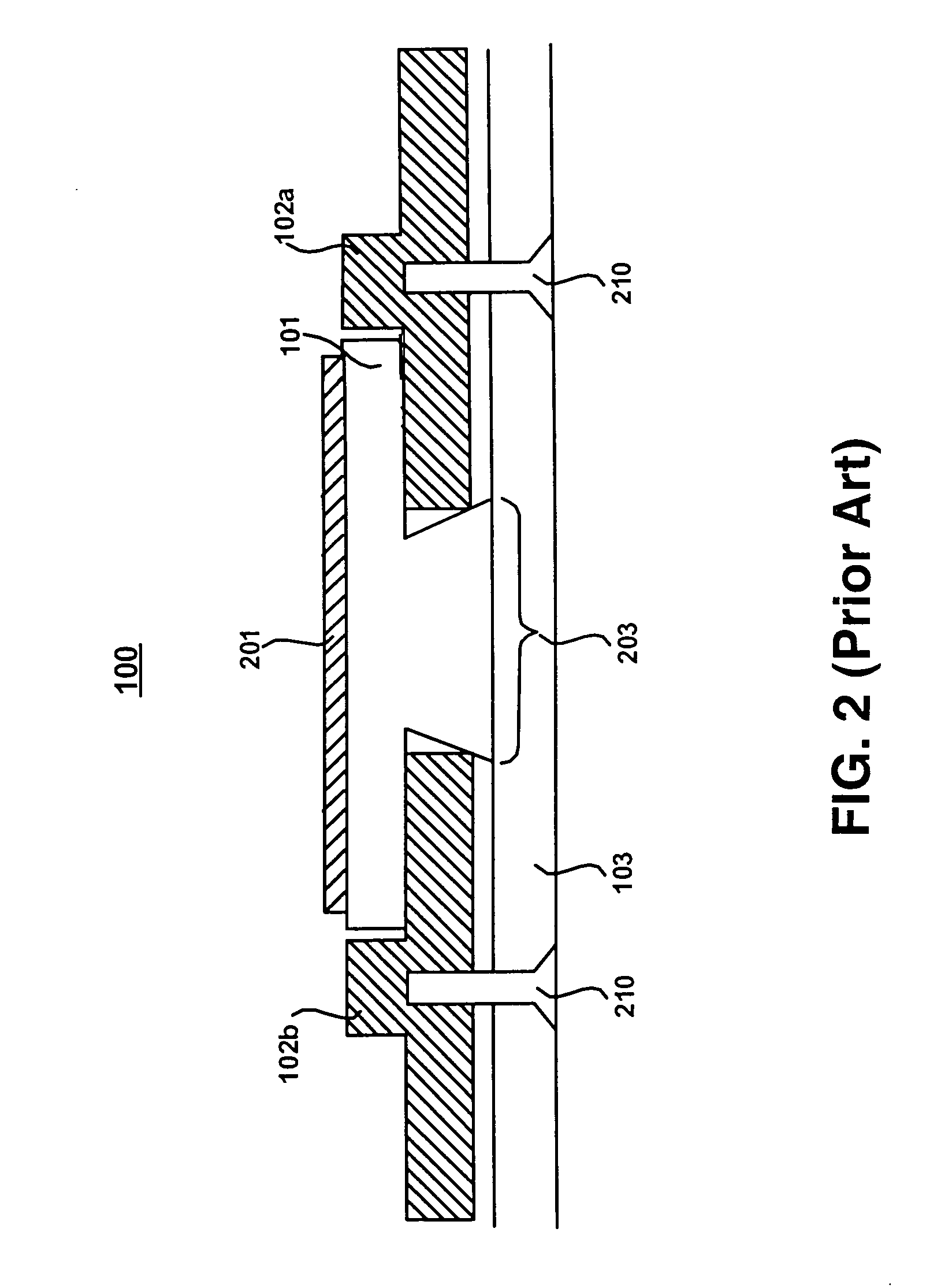
FIELD OF THE INVENTION [0001] Embodiments of the present invention relate to the fabrication of magnetic storage devices. More specifically, embodiments of the present invention are directed to the removal of heat generated during the fabrication of magnetic storage devices. BACKGROUND OF THE INVENTION [0002] Etching processes are often used when shaping the components of magnetic storage devices such as the rails or other air bearing surfaces. An exemplary pallet assembly 100 used for shaping these components is shown in the exploded perspective view of FIG. 1. Pallet assembly 100 comprises a carrier 101 which holds a wafer or other component being etched. During use, a plurality of carriers 101 are slid between arms (e.g., 102a and 102b) of frame 102 which is then coupled with tray 103 using, for example, screws inserted into holes 104. [0003]FIG. 2 shows a section view of pallet assembly 100. During use, a wafer 201 is coupled with carrier 101. As shown in FIG. 2, carrier 101 is ...

Claims


Application Information

Patent Timeline
IPC IPC(8): F25D25/00F25D17/04B65G17/16B65G17/32
CPCH01L21/67109H01L21/67333
Inventor CHEN, PEIGOITIA, JORGEHWANG, CHERNGYELEUNG, BIGALPEREZ, DIANASUN, YONGJIAN
Owner WODEN TECH INC
Why Eureka
Try Eureka