Press Quench Machine

Active Publication Date: 2014-11-06
AGRISOLUTIONS WEAR TECH CORP
View PDF1 Cites 2 Cited by
  • Summary
  • Abstract
  • Description
  • Claims
  • Application Information

AI Technical Summary

Benefits of technology

[0007]A press quench machine designed with a pressure assembly with a plurality of stops and plurality of upper vertical die plates and a plurality lower vertical die plates. Said stops, upper vertical die plates and lower vertical die plates designed to form the structure of a metal object such that w

Problems solved by technology

When a metal object is heated above its curing temperature, the metal object deforms as it cools, losing its original shape and utility unless the metal object is contained within a mold or fr

Method used


Image

  • Press Quench Machine
  • Press Quench Machine
  • Press Quench Machine

Examples


Example

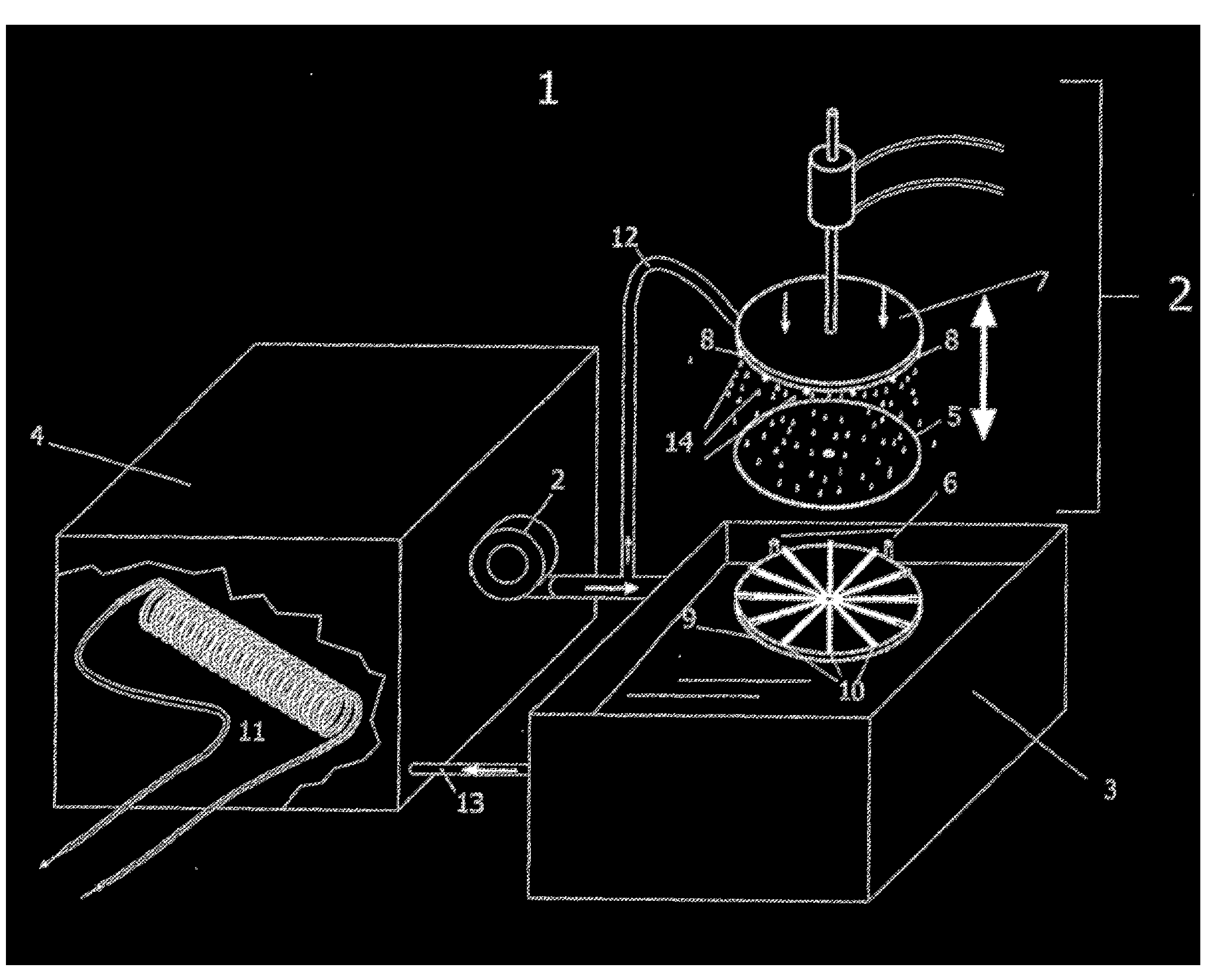
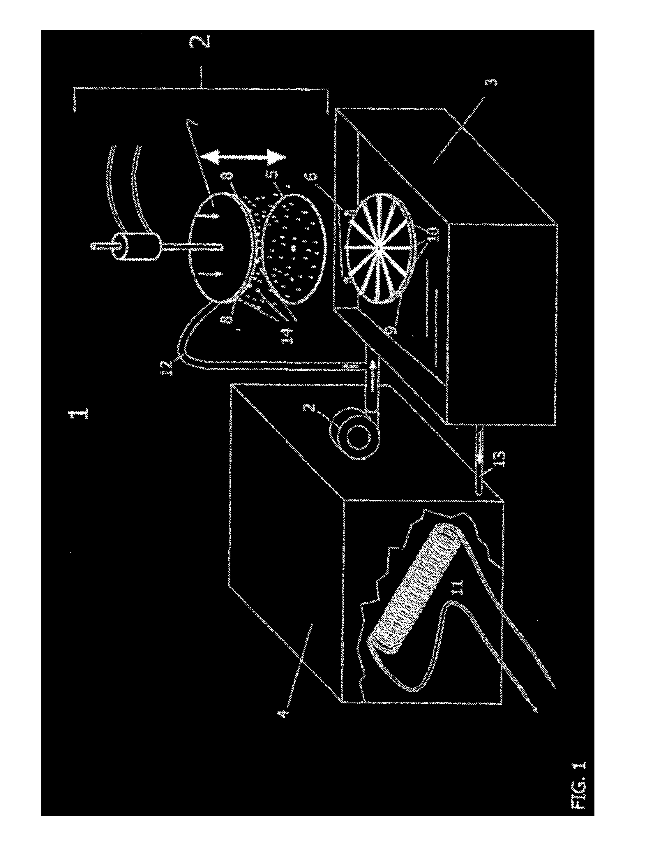
[0013]The press quench machine 1 comprises a pressure assembly 2, a quenchant bath 3 and a recirculation tank 4.

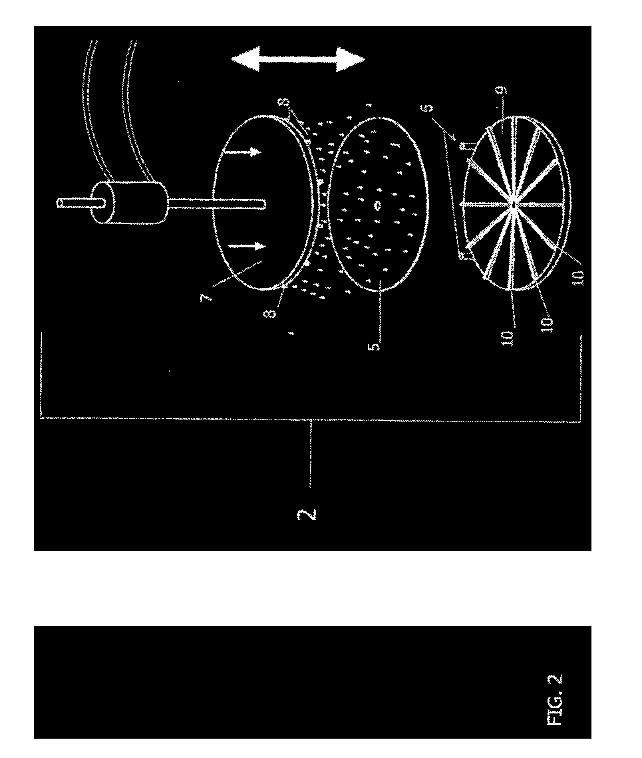
[0014]The pressure assembly 2 is that portion of the press quench machine that holds and applies pressure to a metal object 5 and comprises a plurality of stops 6, an upper base mount 7 with a plurality of upper vertical die plates 8 extending downward from the upper base mount 7, a lower base mount 9 with a plurality of lower vertical die plates 10 extending upward from the lower base mount 9. The plurality of stops 6 ensure that when the metal object 5 is inserted into the pressure assembly 2 the metal object 5 is properly oriented relative to the upper vertical die plates 8 and the lower vertical die plates 10. The upper vertical die plates 8 and the lower vertical die plates 10 are designed so that the ends opposite the respective upper base mount and lower base mount form a framework that along with the plurality of stops 6, create a framework that conforms to the ori...


PUM


Abstract

This invention is an apparatus for cooling a metal object that has been heated above the curing point, such that as the metal object cools, it retains its original shape.

Description

STATEMENT REGARDING FEDERALLY SPONSORED RESEARCH OR DEVELOPMENT[0001]Not ApplicableREFERENCE TO SEQUENCE LISTING, A TABLE, OR A COMPUTER PROGRAM LISTING COMPACT DISC[0002]Not ApplicableDESCRIPTIONField of the invention[0003]This invention is an apparatus for cooling a metal object that has been heated above the curing point such that as the metal object cools the metal object retains its original shape.BACKGROUND OF THE INVENTION[0004]When a metal object is heated above its curing temperature, the metal object deforms as it cools, losing its original shape and utility unless the metal object is contained within a mold or framework. Because of the problem of deformation, a metal object cannot be fabricated in a particular shape and later modified using heating techniques without the metal object becoming deformed. The press quench machine is designed to supply a framework for the metal object's shape such that when the preformed metal object is inserted into the framework, pressure i...

Claims


Application Information

Patent Timeline
IPC IPC(8): C21D1/63C21D1/667
CPCC21D1/667C21D1/63C21D1/18C23C24/10C21D1/673C21D1/70C21D2251/02
Inventor HILL, EARL, E.
Owner AGRISOLUTIONS WEAR TECH CORP
Why Eureka
Try Eureka