Generating method and generating system utilizing combustion exhaust gas

a generating system and generating method technology, applied in the direction of electric generator control, machines/engines, mechanical equipment, etc., can solve the problems of more loss in the high rotation region, and achieve the effect of improving gas volume and pressure, further increasing gas pressure, and further efficiently driving

a generating system and generating method technology, applied in the direction of electric generator control, machines/engines, mechanical equipment, etc., can solve the problems of more loss in the high rotation region, and achieve the effect of improving gas volume and pressure, further increasing gas pressure, and further efficiently driving

US20090278360A1Inactive Publication Date: 2009-11-12TATEOKA TETABUJI

Image

  • Generating method and generating system utilizing combustion exhaust gas
  • Generating method and generating system utilizing combustion exhaust gas
  • Generating method and generating system utilizing combustion exhaust gas

Examples


embodiment 1

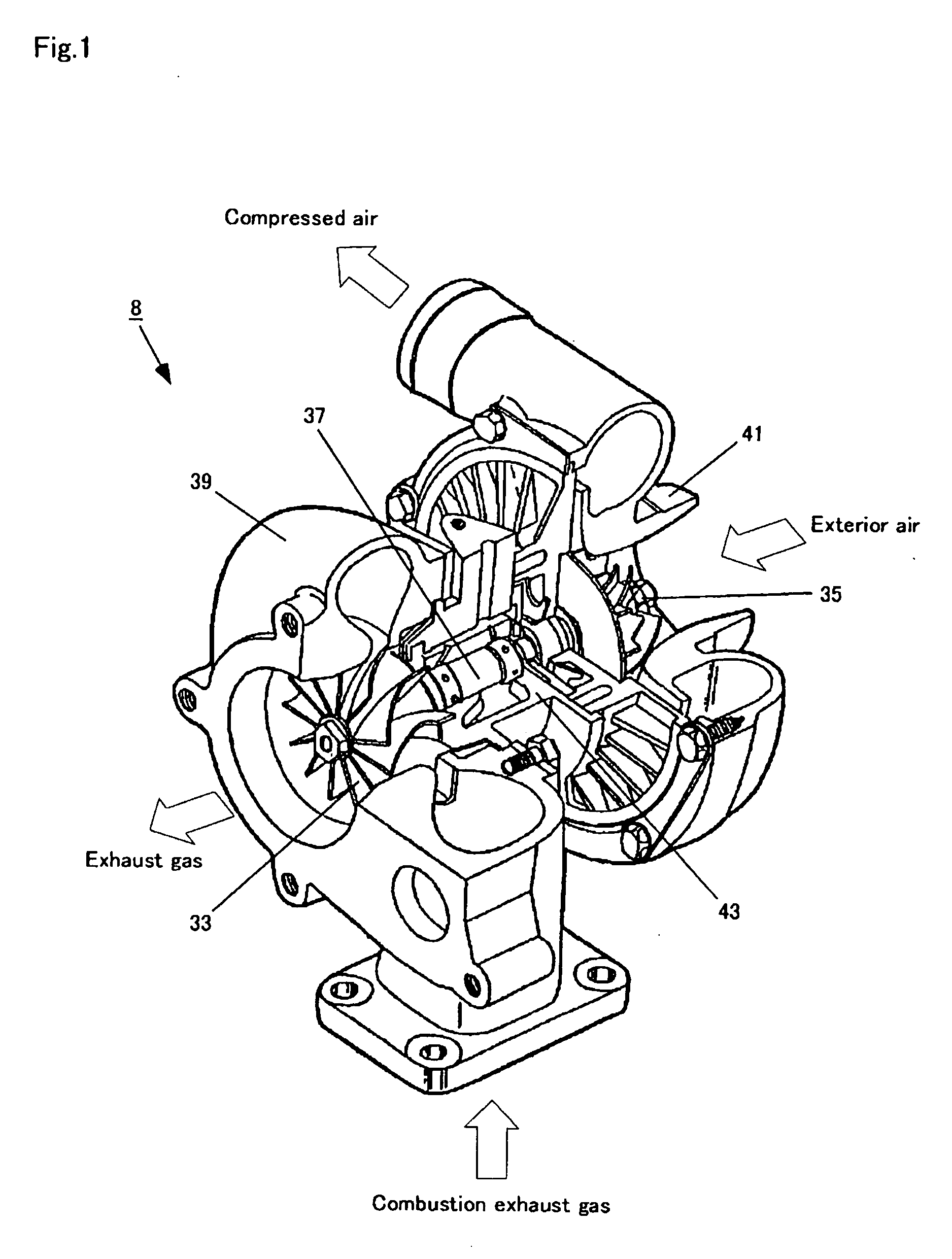
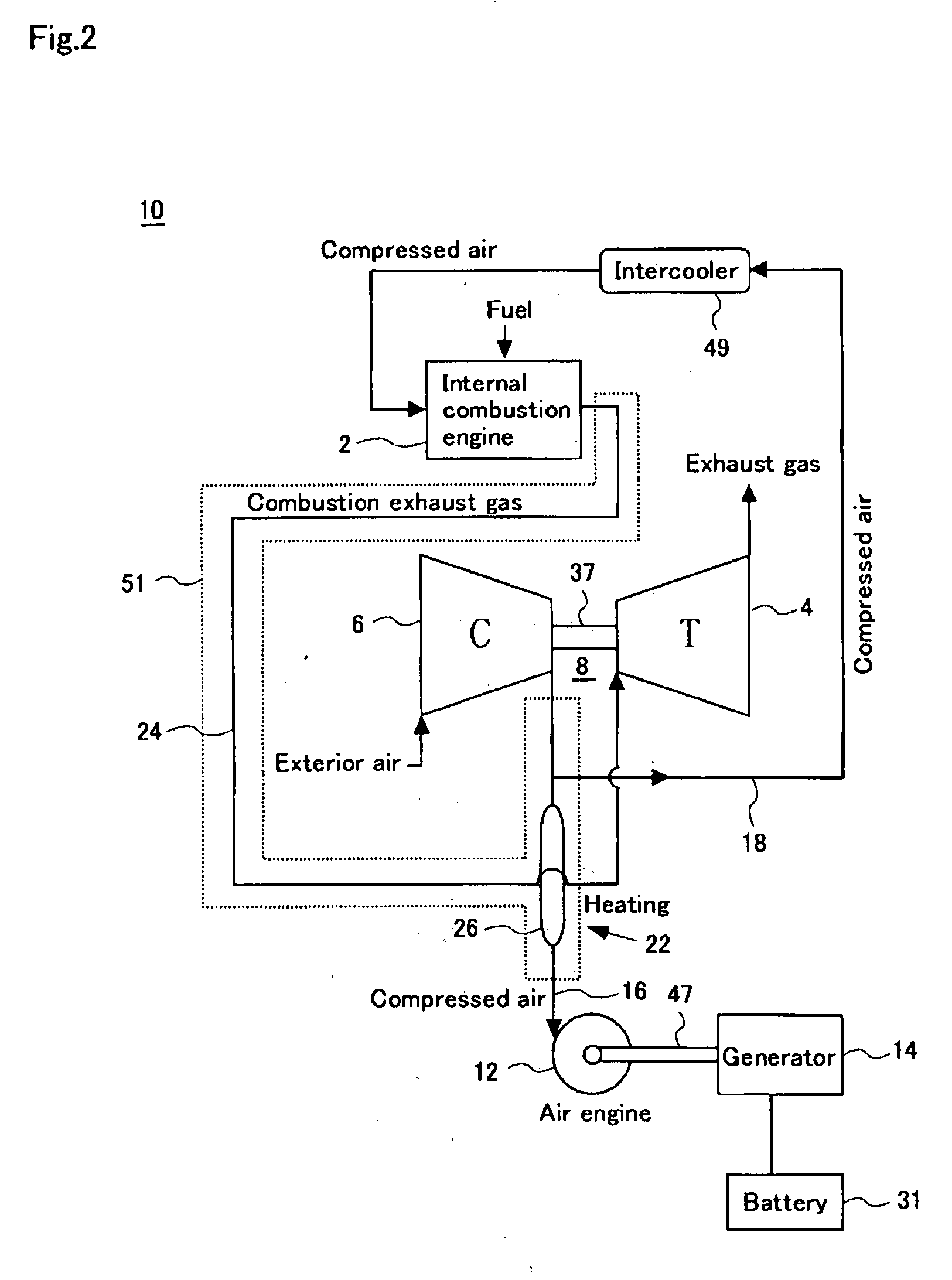
[0063]FIG. 2 is a schematic diagram for explaining a configuration of the generating system using combustion exhaust gas of Embodiment 1.

[0064]The generating system 10 shown in figures is mounted on vehicles such as hybrid passenger cars and trucks running by shifting an engine (internal combustion) and a motor. It is purposed to soup up engine by the turbocharger and exhausted heat of the combustion exhaust gas that has been conventionally wasted is efficiently utilized at the same time.

[0065]This generating system 10 includes the above mentioned turbocharger 8, an air engine 12, a generator 14, and electric storage equipment 31.

[0066]The air engine 12 is an air engine that drives by air pressure of compressed air as disclosed in e.g. Japanese Examined Patent Publication No. JP-B-3306053 and its explanatory website (http: / / homepage3.nify.com / miengns / p2 / airengen.html), or a turbine that blows compressed air to a blade to rotate the blade by air pressure. The engine is not limited to...

embodiment 2

[0082]FIG. 4 is a schematic diagram for showing a generating system utilizing combustion exhaust gas of Embodiment 2. With respect to the configuration similar to the Embodiment 1, the similar numeral reference is put to omit repetition of explanation.

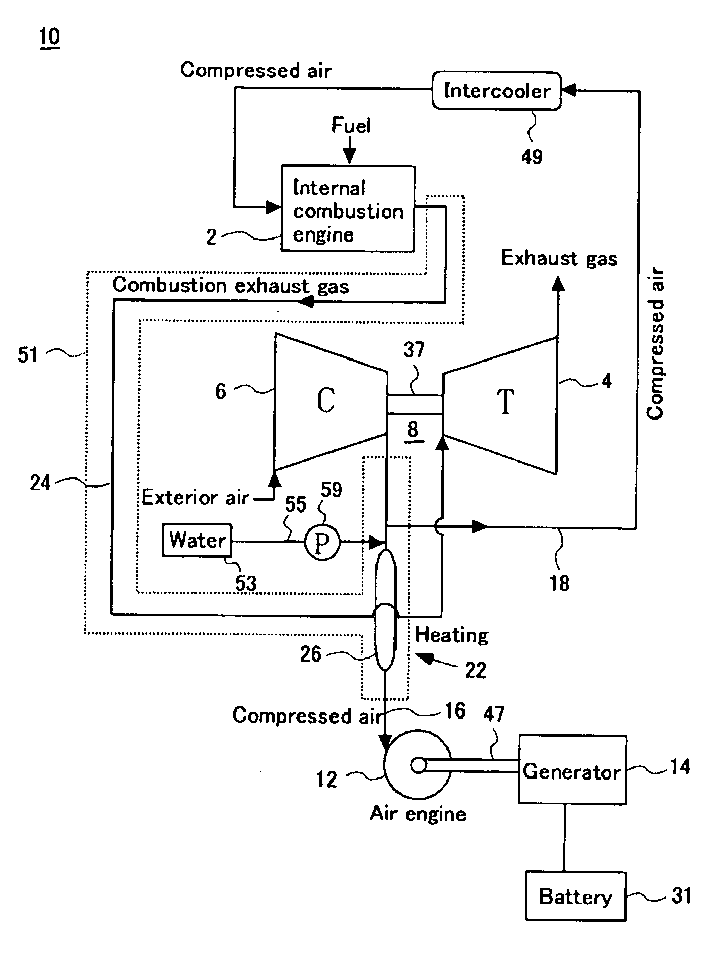
[0083]A generating system 10 of Embodiment 2 is added with a small amount of water inside the driving air supply pipe 16 of the generating system explained in Embodiment 1.

[0084]A portion in front of the chamber portion 26 that is a part of the driving air supply pipe 16 is attached with a water pipe 55 linking to a water tank 53 provided outside. And a nozzle passing through the driving air supply pipe 16 is provided in a connection between the water pipe and the driving air supply pipe 16. And a pump 59 for spraying water inside the driving air supply pipe 16 of high pressure is provided in a path of the water pipe 55.

[0085]From the water tank 53, water is sprayed inside the driving air supply pipe 16 through the water pipe 55 at app...


PUM


Abstract

Gas pressure and exhaust heat of the combustion exhaust gas exhausted from the internal combustion engine is effectively utilized for generating electricity.Using a turbocharger (8) having a turbine (4) that is driven by gas pressure of the combustion exhaust gas and a compressor (6) that is driven by rotational force generated in the turbine, an air engine (12) generating rotational force by air pressure as a power source, and a generator (14) converting the rotational force generated by the air engine to electric power, the air inspired from outside is compressed by the compressor of the turbocharger and heated by the turbine heat at high temperature, and electricity is generated by the generator using the generated compressed air of high pressure and high temperature as a power source of the air engine. The compressed air thus generated in the turbocharger (8) is shared and distributed for combusting the internal combustion engine (2) and for driving the air engine (12).

Description

BACKGROUND OF THE INVENTION[0001]1. Field of the Invention[0002]The present invention relates to a generating method and a generating system utilizing combustion exhaust gas to effectively use gas pressure and exhaust heat of combustion exhaust gas discharged from internal combustion engines.[0003]2. Background of the Invention[0004]Recently, internal combustion engines (engines) have increasingly installed supercharging devices such as turbochargers and supercharger to obtain large power output in case of necessity.[0005]The turbocharger effectively utilizes exhaust gas pressure of exhaust gas that has been wasted in conventional naturally-aspirated engines. And the turbocharger is a supercharging device that provides rotational force to shafts by a force of combustion exhaust gas of the engine, thereby rotating a coaxial compressor to increase amount of intake air. Although 30% to 40% energy of fuel is wasted in the air as combustion exhaust gas in general engines, energy of this ...

Claims


Application Information

Patent Timeline
12 Nov 2009
Publication
US20090278360A1
IPC
H02K7/18; F02C6/04
CPC
F01D15/10; F01N5/02; F01N2240/02; F02B37/164; F02B41/10; F05D2220/40; F02C6/12; Y02T10/144
Inventors
TATEOKA, TETSUJI