[0017]With the engine of the present invention, the valve stopping mechanism is constructed to generate the operating state when the energizing force of the operation energizing member is larger than the press force of the stop hydraulic
fluid pressure, and generates the stop state when the press force of the stop hydraulic
fluid pressure is larger than the energizing force of the operation energizing member. When the engine is operated at very
low speed at the time of start of the engine or the like and the stop hydraulic fluid pressure is low, a valve operating state is generated, and a cylinder operating state is obtained. Consequently, a large engine output can be obtained with reliability as a cylinder operating state upon the start of the engine.
[0018]In the stop hydraulic fluid pressure supply controller, the switching member is moved to the hydraulic
fluid supply position side by the energizing force of the switching energizing member, and the pressure force is applied from the switching pressure supply control mechanism to move the hydraulic fluid
discharge position side. Consequently, at the time of switching the cylinder stop state to the cylinder operating state, the pressure force is applied from the switching pressure supply control mechanism and a control of moving the switching member to the hydraulic fluid
discharge position is performed. Since the control of forcedly moving the switching member by using the pressure force is performed, a control of promptly moving the switching member to the hydraulic fluid
discharge position can be performed, and the response of a switch from the cylinder stop state to the cylinder operating state can be improved. Consequently, in the case such that the driver performs an operation of opening the
throttle in the cylinder operating state, the state is promptly switched to the cylinder operating state, and the response to a request for increasing an engine output can be improved.
[0019]In the engine, preferably, the switching pressure supply control mechanism is constructed by a
solenoid valve and, when a solenoid is energized, a control of applying the pressure force so as to move the switching member to the hydraulic fluid discharge position side is performed. With this configuration, the cylinder operating state and the cylinder stop state can be easily switched by the control of passing current to the solenoid.
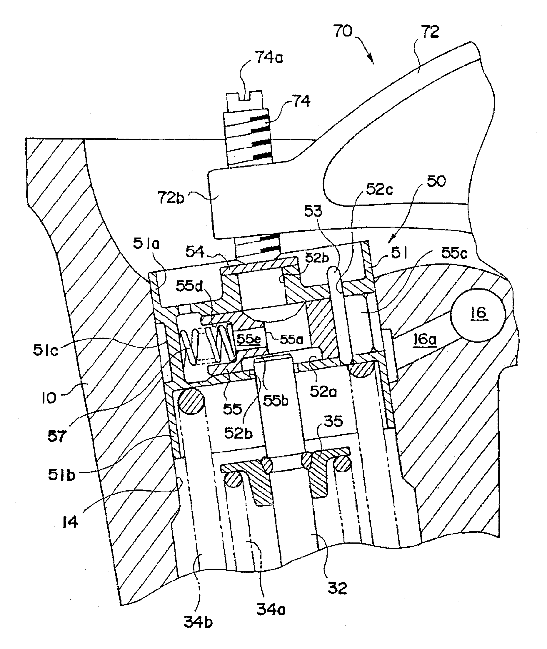
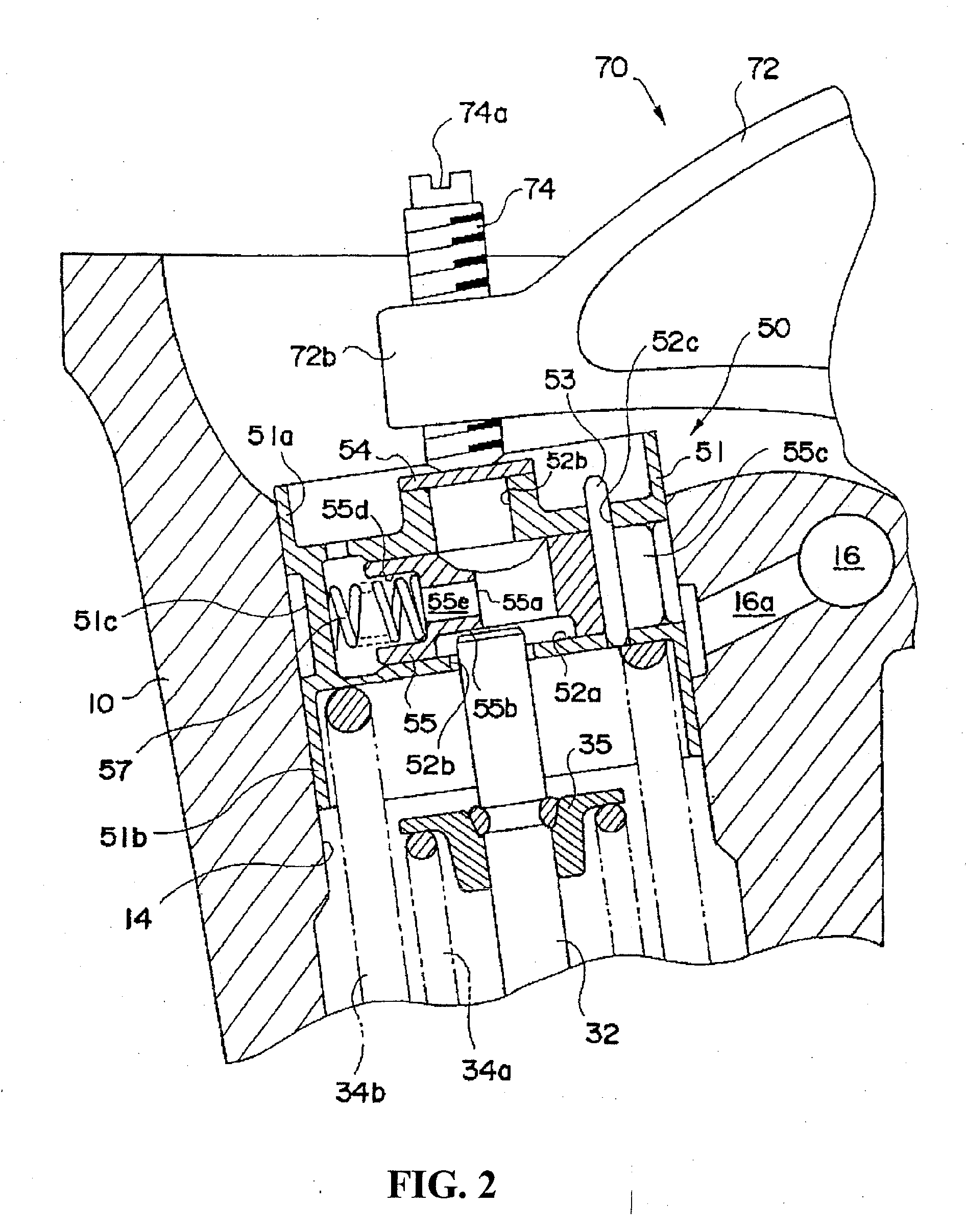
[0020]In the engine, preferably, the valve stopping mechanism includes a holder reciprocated by the valve drive
cam and a stop selecting member capable of moving between an operating position to open / close the valve in accordance with the reciprocating operation of the holder and a stop position to hold the valve in a valve close position irrespective of the reciprocating operation of the holder. The operation energizing member energizes the stop selecting member to the operation position side, and the stop selecting member which receives the stop hydraulic fluid pressure is pressed to the stop position side against the energizing force of the energizing member. With such a configuration, the operation control of setting the valve stopping mechanism in the stop position or the operating position on the basis of the balance between the energizing member and the stop hydraulic fluid pressure can be performed easily and reliably.
[0021]In this case, in the stop selecting member, a stem
abutment face and a stem receiving part are formed. When the stop selecting member is in the operating position, the stem
abutment face abuts on the tip of the
valve stem and moves the valve in the open / close direction together with the holder. When the stop selecting member is in the stop position, the tip of the
valve stem is fit in the stem receiving part, and the stem receiving part moves the holder but maintains the valve closed. The stem
abutment face and the stem receiving part are formed adjacent to each other, and the stop hydraulic fluid pressure is received on the side opposite to the stem abutment face. With this configuration, in the stop selecting member, the stem abutment face for receiving the press force from the
valve stem and the portion for receiving the stop hydraulic fluid pressure are apart from each other via the stem receiving part. Consequently, the influence of the press force acting from the valve stem to the stem abutment face, exerted on the part of receiving the stop hydraulic fluid pressure is suppressed. Therefore, deformation of the portion for receiving the stop hydraulic fluid pressure is small, the sealing performance of the portion is maintained excellent, and durability can be improved.
[0022]Further, in the stop selecting member, when the energizing member housing part is formed on the same side as the side on which the stem abutment face is formed, and a stem communication hole is provided in a position overlapping the stem abutment face, the stem communication hole becomes longer, the weight of the stop selecting member can be reduced by that amount, and response at the time of moving the stop selecting member improves. Thus, the weight of the whole valve stop mechanism is reduced.

