
Muffler valve device for vehicle

Active Publication Date: 2019-04-25
HYUNDAI MOTOR CO LTD +1
View PDF11 Cites 0 Cited by
  • Summary
  • Abstract
  • Description
  • Claims
  • Application Information

AI Technical Summary

Benefits of technology

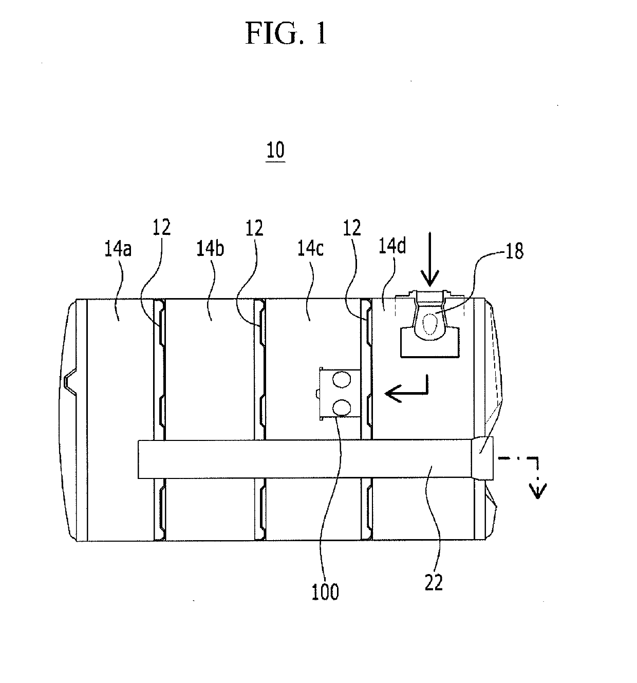
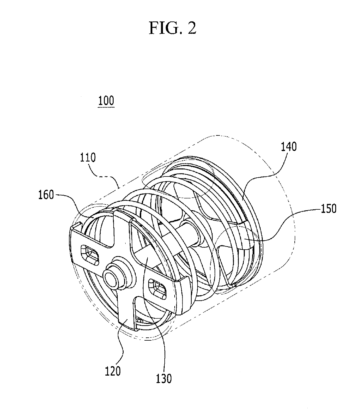
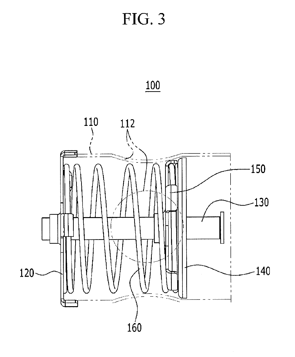
The present invention provides a muffler valve device for a vehicle that can adjust the flow of exhaust gas based on pressure from the engine to improve engine output and reduce noise. This can be done while keeping the structure simple and reducing manufacturing costs. The device consists of a chamber, guide rod, fixing member, and valve, which work together to adjust the flow of exhaust gas and provide an elastic force. Overall, this invention can enhance engine performance while reducing noise and flow-induced noise.

Problems solved by technology

However, although the conventional muffler obtains effect of reducing the booming sound by mounting the variable valve opens and closes according to the pressure of the exhaust gas, the variable valve includes a housing, a gate, a gate rotation shaft, a spring and a protrusion portion etc., therefore the structure is complex, and manufacturing cost according to increasing of components is increased, and a weight is increased.

Method used


Image

  • Muffler valve device for vehicle
  • Muffler valve device for vehicle
  • Muffler valve device for vehicle

Examples


Embodiment Construction

[0033]Reference will now be made in detail to various embodiments of the present invention(s), examples of which are illustrated in the accompanying drawings and described below. While the invention(s) will be described in conjunction with exemplary embodiments, it will be understood that the present description is not intended to limit the invention(s) to those exemplary embodiments. On the contrary, the invention(s) is / are intended to cover not only the exemplary embodiments, but also various alternatives, modifications, equivalents and other embodiments, which may be included within the spirit and scope of the invention as defined by the appended claims.

[0034]In the following detailed description, only certain exemplary embodiments of the present invention have been shown and described, simply by way of illustration. As those skilled in the art would realize, the described embodiments may be modified in various different ways, all without departing from the spirit or scope of the...


PUM


Abstract

A muffler valve device for a vehicle may include a chamber fixed at a surface of the wall, a guide rod provided in the chamber and attached at the surface of the wall, a fixing member attached at one end portion of the guide rod and fixing the chamber, a valve disposed slidably on the guide rod between the surface of the wall and the fixing member, and an elastic member located between the valve and the fixing member to provide an elastic force to the valve.

Description

CROSS-REFERENCE TO RELATED APPLICATION[0001]The present application claims priority to Indian Patent Application No. 201711037738 filed in the Indian Patent Office on Oct. 25, 2017, the entire contents of which is incorporated herein for all purposes by this reference.BACKGROUND OF THE INVENTIONField of the Invention[0002]The present invention relates to a muffler valve device for a vehicle. More particularly, the present invention relates to a muffler valve device for a vehicle, more particularly, to adjust flowing of exhaust gas according to pressure of the exhaust gas exhausted from an engine to enhance the engine output and reduce booming noise and flow-induced noise.Description of Related Art[0003]Generally, an exhaust apparatus for a vehicle is for exhausting the high temperature and high pressure exhaust gas to outside through exhaust stroke. The exhaust apparatus includes an exhaust manifold gathering combustion gas exhausted from each cylinder, an exhaust pipe inducing the ...

Claims


Application Information

Patent Timeline
IPC IPC(8): F01N1/16
CPCF01N1/163F01N1/083F01N1/089F01N1/16F01N1/166F01N2290/00F01N2390/00F01N2390/06F01N2470/18F01N2410/14
Inventor KUMAR, CHINTALA CHYTANYAOH, MAN SEOKMITTA, MUKESH REDDYV, KIRAN
Owner HYUNDAI MOTOR CO LTD
Learn More