Engine system

a technology of engine and system components, applied in the direction of charge feed system, electric control, non-fuel substance addition to fuel, etc., can solve the problems of reducing the output of the engine, inhibiting the combustion, and affecting the combustion inside the engine, so as to improve the engine's thermal efficiency, reduce the influence of water injection on the combustion, and improve the engine's output

Pending Publication Date: 2022-03-03
MAZDA MOTOR CORP
View PDF1 Cites 0 Cited by
  • Summary
  • Abstract
  • Description
  • Claims
  • Application Information

AI Technical Summary

Benefits of technology

[0010]The engine system may further include a heat exchanger provided to an exhaust pipe of the engine and configured to heat water with heat of exhaust gas of the engine. The water heated by the heat exchanger may be supplied to the water injector. According to this configuration, since water to be injected into the combustion chamber by the water injector is heated by utilizing the heat of the exhaust gas, the exhaust heat is recovered, and thereby thermal efficiency of the engine improves.
[0011]According to another aspect of the present disclosure, an engine system is provided, which includes an engine configured to generate a motive force for a vehicle by combusting a mixture gas of fuel and intake air, a water injector configured to inject heated water into a combustion chamber of the engine, and a controller configured to control the water injector to inject the water into the combustion chamber during an expansion stroke of the engine. The controller acquires a demanded engine load of the engine, and controls the water injector to retard a start timing of the water injection as the demanded engine load increases. Also according to this configuration, the influence of the water injection on the combustion can be reduced when the engine load is comparatively high, and the improvement in the output of the engine by the water injection can be secured.
[0012]The controller may control the water injector to advance the start timing of the water injection as the demanded engine load decreases.
[0013]The controller may control the water injector to increase an amount of water injection as the demanded engine load decreases.
[0014]The controller may change a ratio of an amount of water injection to an amount of fuel injection, and control the water injector to increase the amount of water injection as the demanded engine load decreases.

Problems solved by technology

However, when water is injected during the expansion stroke as disclosed in JP2009-168039A, the water injection may affect combustion inside the engine.
That is, the water injection during the expansion stroke may cause diffusion of water vapor inside the combustion chamber where the combustion is in progress, and thus, the water vapor may inhibit the combustion (e.g., in an engine which performs SI (Spark Ignition) combustion, water vapor inhibits flame propagation).
As a result, the water injection aimed at improving the output of the engine may rather reduce a combustion work of the engine.

Method used


Image

  • Engine system
  • Engine system
  • Engine system

Examples


Embodiment Construction

[0022]Hereinafter, engine systems according to embodiments of the present disclosure are described with reference to the accompanying drawings.

[Configuration of Engine System]

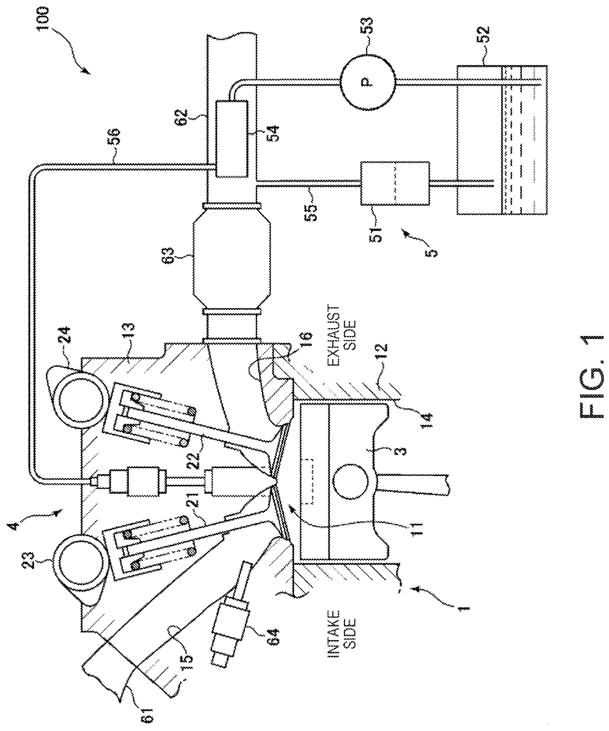
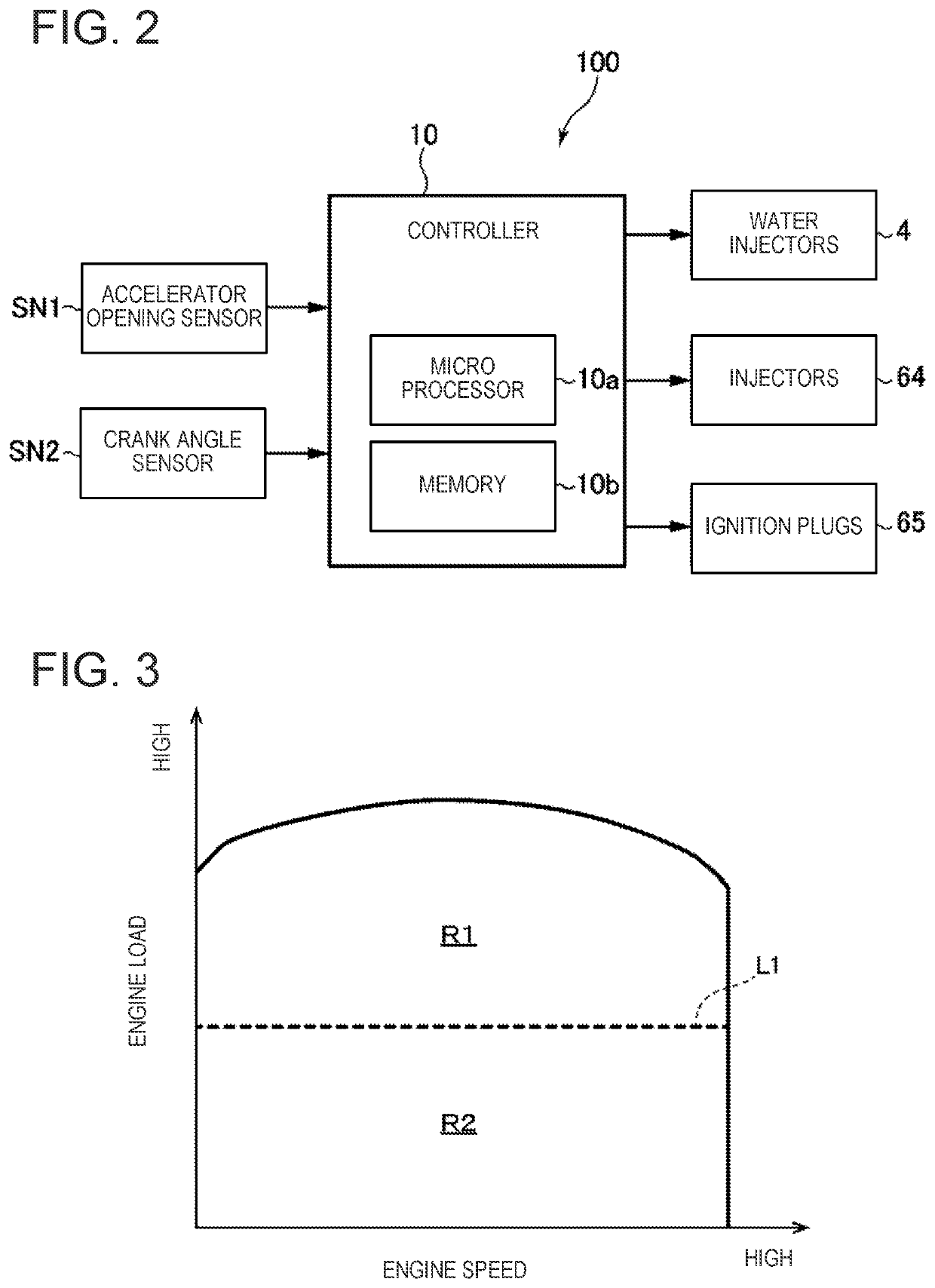
[0023]First, a configuration of an engine system according to one embodiment of the present disclosure is described with reference to FIGS. 1 and 2. FIG. 1 is a schematic view illustrating the configuration of the engine system according to this embodiment. FIG. 2 is a block diagram illustrating an electrical configuration of the engine system according to this embodiment.

[0024]As illustrated in FIG. 1, an engine system 100 according to this embodiment mainly includes an engine 1 which generates a motive force for a vehicle by combusting a mixture gas of fuel and air, a water injector 4 which injects water into the engine 1, and a water supplier 5 which supplies water to the water injector 4. The engine 1 is a four-stroke reciprocating engine which operates by repeating an intake stroke, a compression stroke, a...


PUM


Abstract

An engine system is provided, which includes an engine configured to generate a motive force for a vehicle by combusting a mixture gas of fuel and intake air, a water injector configured to inject heated water into a combustion chamber of the engine, and a controller configured to control the water injector to inject the water into the combustion chamber during an expansion stroke of the engine. The controller acquires a demanded engine load of the engine, and controls the water injector to retard a start timing of the water injection when the demanded engine load is within a first-load range, compared to when the demanded engine load is within a second-load range where the engine load is lower than in the first-load range.

Description

TECHNICAL FIELD[0001]The present disclosure relates to an engine system which injects water into a combustion chamber of an engine.BACKGROUND OF THE DISCLOSURE[0002]For example, JP2009-168039A discloses this type of technology. In detail, JP2009-168039A discloses a technology for a compression ignition engine in which a mixture gas is combusted by compression ignition. In this technology, heated water, in particular, subcritical water at or above 250° C. and at or above 10 MPa, is injected into a combustion chamber during a compression stroke and an expansion stroke. Such an injection of water into the combustion chamber improves emissions (e.g., reduces emissions of NOx and CO), and the output of the engine.[0003]However, when water is injected during the expansion stroke as disclosed in JP2009-168039A, the water injection may affect combustion inside the engine. That is, the water injection during the expansion stroke may cause diffusion of water vapor inside the combustion chambe...

Claims


Application Information

Patent Timeline
Patent Type & Authority Applications(United States)
IPC IPC(8): F02M25/022F02M25/03
CPCF02M25/0224F02M25/0222F02M25/0227F02M25/03F02D19/12F02D41/0025F02B47/02F02M25/0221
Inventor NAGASAWAKIYOSUE, RYO
Owner MAZDA MOTOR CORP
Why Eureka
Try Eureka