
Variable compression ratio device

a compression ratio and variable technology, applied in the direction of positive displacement engines, machines/engines, mechanical equipment, etc., can solve the problems of limited advance of ignition timing, engine output may deteriorate, engine damage, etc., to improve the output of the engine and reduce the fuel consumption

Active Publication Date: 2018-03-29
HYUNDAI MOTOR CO LTD
View PDF3 Cites 2 Cited by
  • Summary
  • Abstract
  • Description
  • Claims
  • Application Information

AI Technical Summary

Benefits of technology

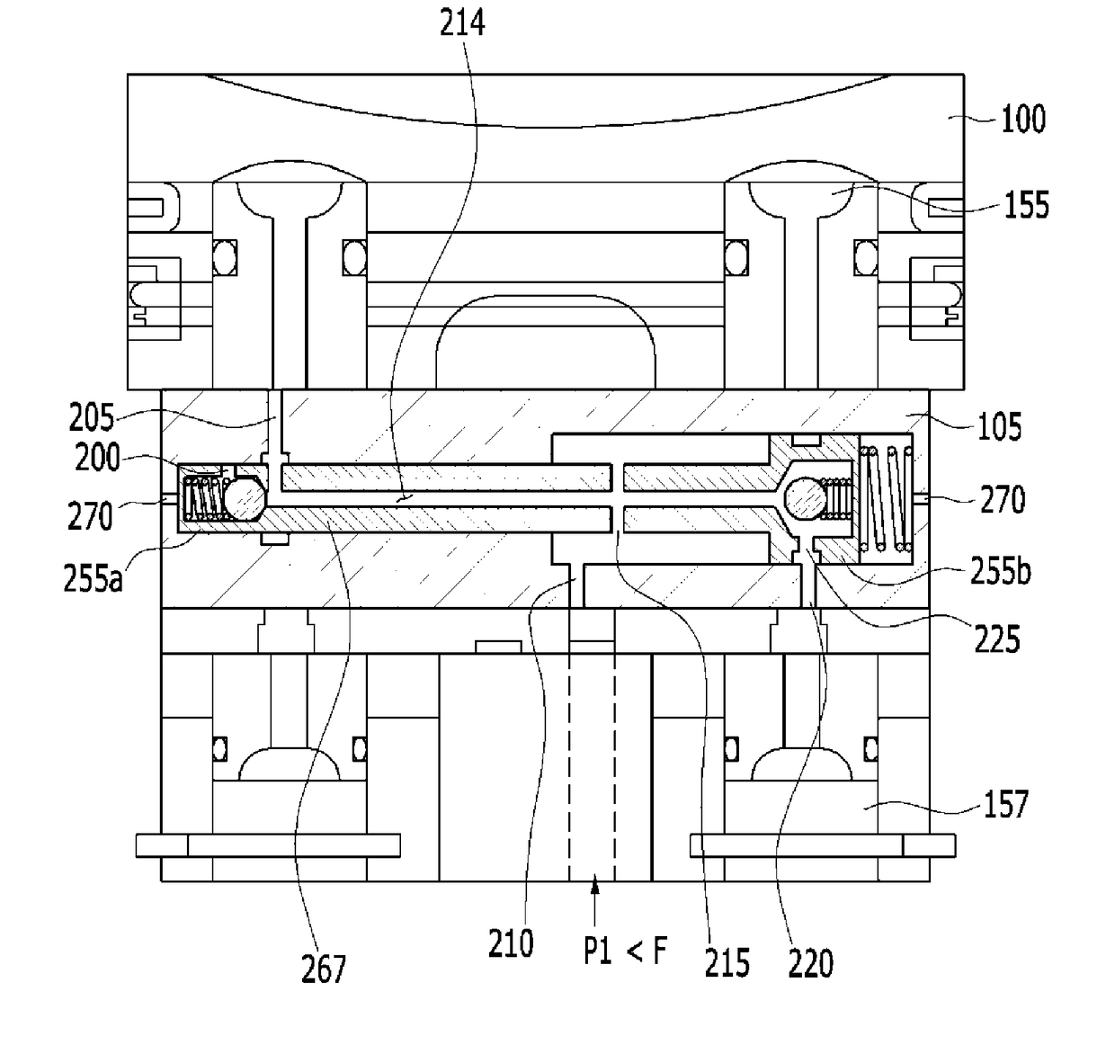
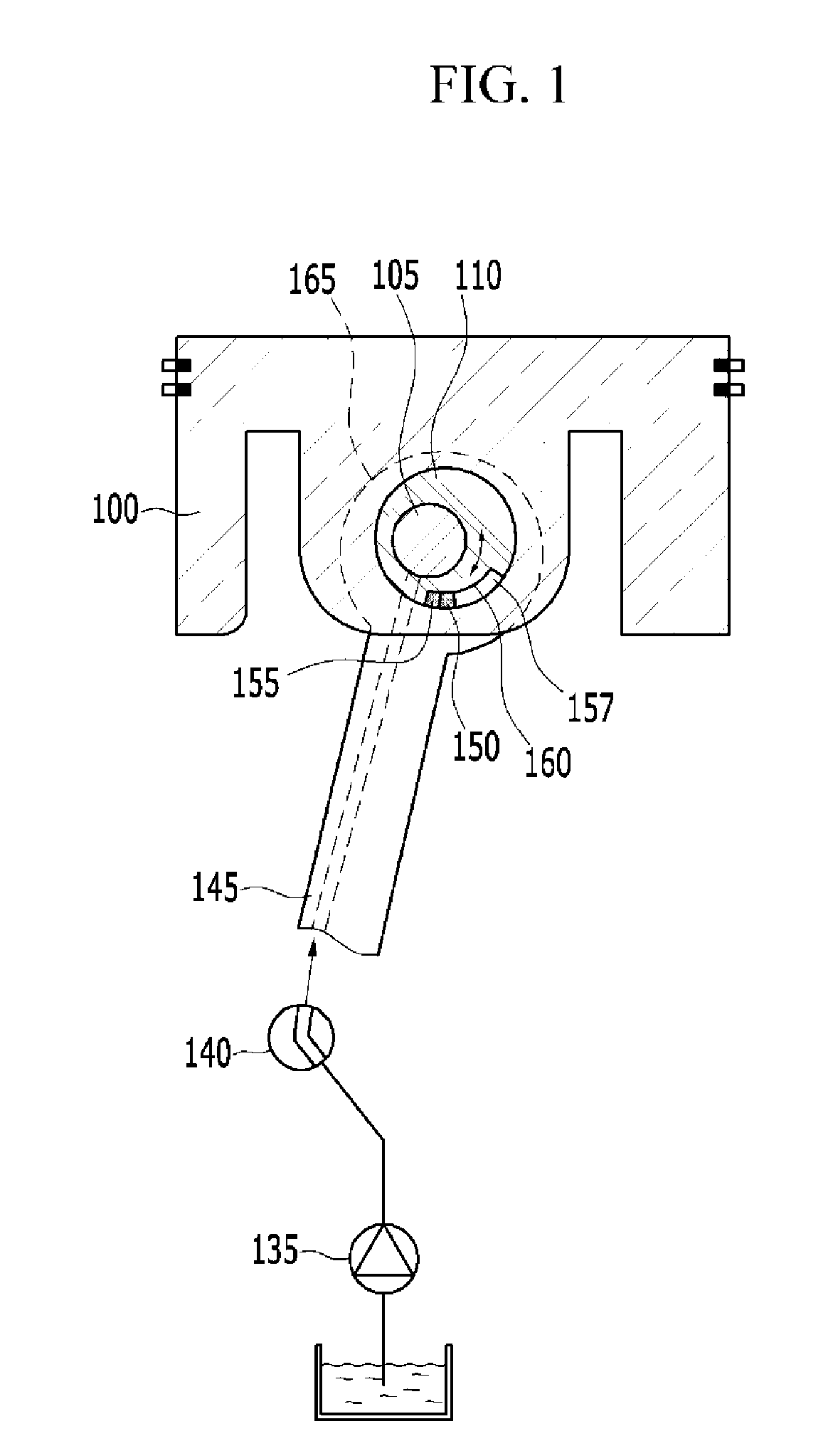
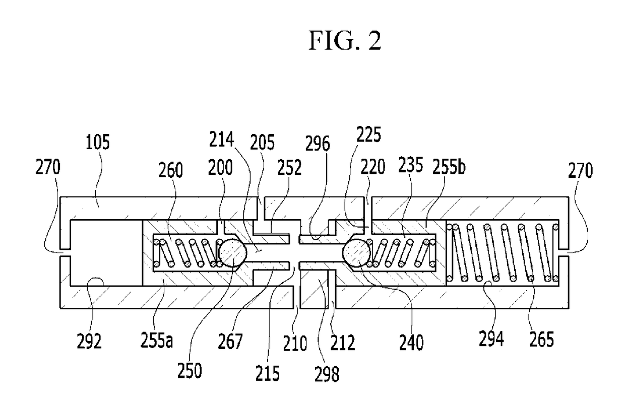
The present invention is about a device that changes the compression ratio of a mixer based on the engine's operating conditions to decrease fuel consumption and improve output. The device has a control valve structure that effectively controls the hydraulic pressure to easily implement high and low compression ratios. This allows for a quick and accurate movement of the check valve and plunger to quickly return oil to the high pressure part, resulting in quick and accurate implementation of both high and low compression ratios.

Problems solved by technology

However, in the case of the spark ignition engine, if the ignition timing is advanced at a high combustion ratio, an abnormal combustion occurs, and therefore the engine may be damaged.
As a result, the advance of the ignition timing is limited, and therefore an output of the engine may deteriorate.
In the case of the current diesel engine, to meet tightened exhaust gas regulations, a volume of a piston combustion chamber is increased to reduce the compression ratio, thereby implementing low temperature combustion and since cold starting performance deteriorates as the compression ratio is decreased, a glow system needs to be made of a ceramic material for strengthening rigidity thereof and a separate control unit for controlling the glow system needs to be added, such that manufacturing costs thereof may be increased.

Method used


Image

  • Variable compression ratio device
  • Variable compression ratio device
  • Variable compression ratio device

Examples


Embodiment Construction

[0046]Reference will now be made in detail to various embodiments of the present invention(s), examples of which are illustrated in the accompanying drawings and described below. While the invention(s) will be described in conjunction with exemplary embodiments, it will be understood that the present description is not intended to limit the invention(s) to those exemplary embodiments. On the contrary, the invention(s) is / are intended to cover not only the exemplary embodiments, but also various alternatives, modifications, equivalents and other embodiments, which may be included within the spirit and scope of the invention as defined by the appended claims.

[0047]Hereinafter, an exemplary embodiment of the present invention will be described in detail with reference to the accompanying drawings.

[0048]However, since sizes and thicknesses of the respective components were arbitrarily shown in the accompanying drawings for convenience of explanation, the present invention is not necessa...


PUM


Abstract

A variable compression ratio device may include a piston pin having first and second plunger spaces, a plunger device including a first plunger that is disposed to reciprocate in the first plunger space, a second plunger and a connection pipe that connects between the first and second plungers, a first check valve disposed in a first check space to move oil from a pipe passage to the first check space in a first direction, a second check valve disposed in a second check space to move the oil from the pipe passage to a second check space in a second direction; and a return member elastically supporting the second plunger to one side.

Description

CROSS-REFERENCE TO RELATED APPLICATION[0001]The present application claims priority to Korean Patent Application No. 10-2016-0123277 filed on Sep. 26, 2016, the entire contents of which is incorporated herein for all purposes by this reference.BACKGROUND OF THE INVENTIONField of the Invention[0002]The present invention relates to an internal combustion engine, and more particularly, to a variable compression ratio device configured for improving fuel efficiency and improving an output of an internal combustion engine by changing a compression ratio within a combustion chamber of the internal combustion engine depending on operation conditions of the engine.Description of Related Art[0003]Generally, thermal efficiency of a heat engine is increased as a compression ratio is increased. In the case of a spark ignition engine, if ignition timing is advanced up to a predetermined level, the thermal efficiency is increased.[0004]However, in the case of the spark ignition engine, if the ign...

Claims


Application Information

Patent Timeline
Patent Type & Authority Applications(United States)
IPC IPC(8): F02B75/04F16J1/16F16C7/06
CPCF02B75/04F16C7/06F16J1/16F16C3/18F16C7/023F02B75/044F01B9/02F02B75/045F02B75/32F02D15/02
Inventor KIM, WON GYUCHOI, MYUNGSIKHWANG, GYU HAN
Owner HYUNDAI MOTOR CO LTD
Learn More