Frequency conversion laser head

Active Publication Date: 2009-11-12
IPG PHOTONICS CORP
19 Cites 8 Cited by

AI-Extracted Technical Summary

Problems solved by technology

The high intensities are accompanied by elevated temperatures which are detrimental to the desired functionality of a laser head explained in detail immediately hereinbelow.
In fact, only a small portion of the pumped light is usefully converted; the other, large portion of the pumped radiation remains unchanged and, therefore, useless.
For example, the pump light, coupled to laser head 14, has a power of 10 W. As a result of the frequency conversion, the o...

Benefits of technology

[0012]Evacuating the unconverted light from a laser head allows for a compact structure of the laser head and mini...

Abstract

A laser assembly is configured with a frequency conversion laser head operative to shift a fundamental frequency of input light to the desired frequency of an output light. The frequency conversion laser head includes a dump means operative to guide an unconverted output light at the fundamental frequency outside the case of the frequency conversion laser head. The dump means is configured with a guide optics operative to couple the output light at the fundamental frequency to a fiber terminating outside the case of the frequency conversion laser head.

Application Domain

Laser using scattering effectsSemiconductor laser structural details +3

Technology Topic

OptoelectronicsFundamental frequency +3

Image

  • Frequency conversion laser head
  • Frequency conversion laser head
  • Frequency conversion laser head

Examples

  • Experimental program(1)

Example

[0019]Reference will now be made in detail to the disclosed system. Wherever possible, same or similar reference numerals are used in the drawings and the description to refer to the same or like parts or steps. The drawings are in simplified form and are far from precise scale. For purposes of convenience and clarity only, the terms “connect,”“couple,” and similar terms with their inflectional morphemes do not necessarily denote direct and immediate connections, but also include connections through mediate elements or devices.
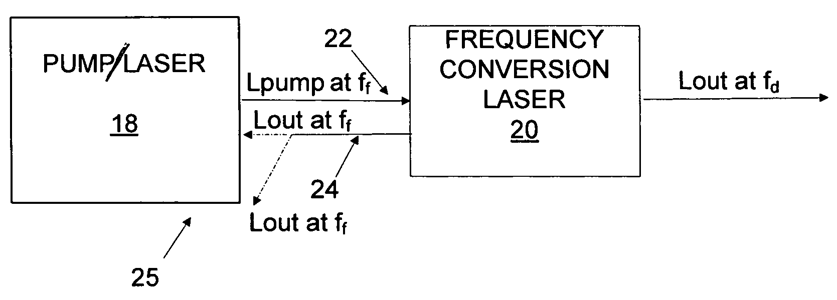
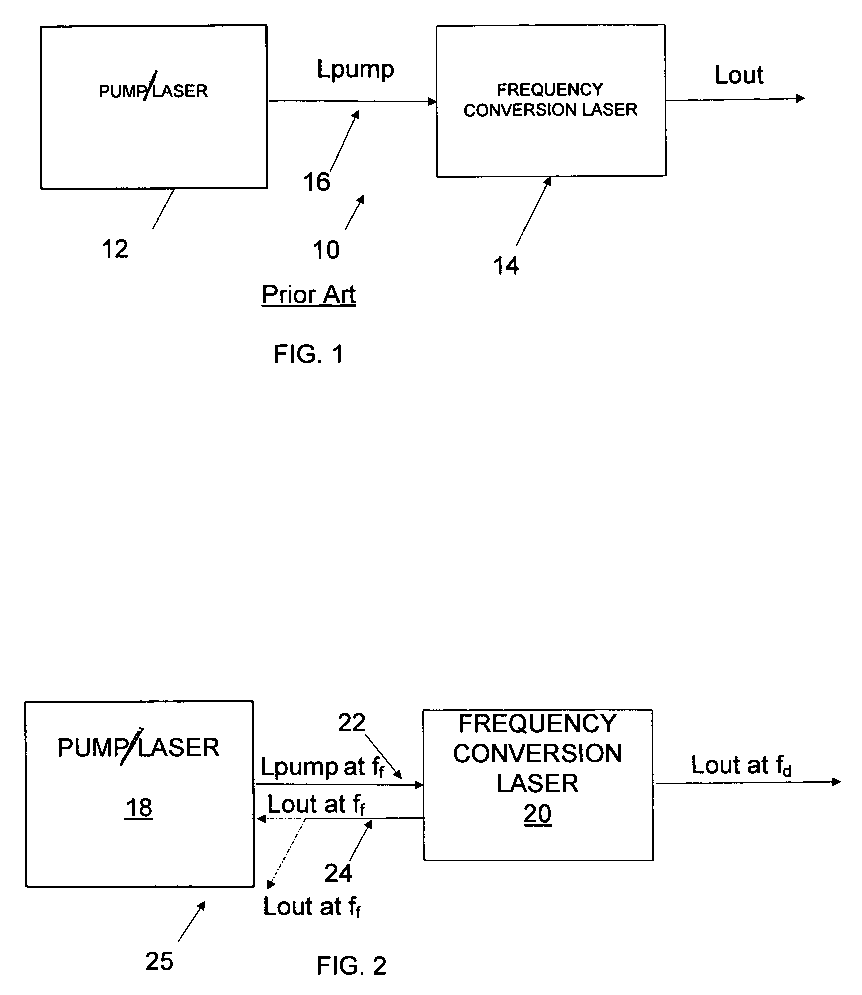
[0020]FIG. 2 illustrates a diagrammatic view of the disclosed laser assembly 25 including a laser system or pump laser module 18 and a frequency conversion laser head 20. An input component 22 couples a pump light beam Lpump at a fundamental frequency ff to frequency conversion laser head 20, which is operative to shift the fundamental frequency ff of pump light Lpump to a desired frequency fd. The light Lpump is processed inside the case of laser head 20 so that it splits into an output light beam Lout at the desired frequency fd and an output light Lout at the fundamental frequency ff, as explained hereinbelow.
[0021]In accordance with one aspect of the disclosure, light Lout at fundamental frequency ff is coupled into a dump fiber 24 guiding light Lout outside frequency conversion laser head 20. As a consequence and in contrast to the known prior art, the heat generated by the reflected light beam does not accumulate inside the laser head that, thus, does not experience overheating while featuring a compact structure.
[0022]Referring to FIGS. 3A and 3B, frequency conversion laser head 20 may be configured as a separate component detachably coupled to laser system or pump laser module 18, or may be manufactured and marketed in combination therewith. In either configuration, frequency conversion laser head 20 may be coupled to system 18, so that these components are displaceably fixed to one another in a single case (FIG. 3B). In accordance with this modification, input and output dump fiber waveguides 22 and 24, respectively, are mounted inside laser system 18. Alternatively, as shown in FIG. 3A, frequency conversion laser 20 is configured as a separate component flexibly coupled to system 18 so that these two components are detachably coupled to and displaceable relative to one another. Typically, laser module 18 and head 20 are coupled by a flexible hollow component 26 (FIG. 3A) which houses input fiber 22 and dump fiber 26.
[0023]FIG. 4 illustrates an optical schematic of disclosed assembly 25 in which frequency conversion laser head 20 is detachably coupled to input fiber waveguide 22 guiding pump light Lpump at fundamental frequency ff from pump 18. The input fiber waveguide 22 outputs the Lpump light beam inside the case of laser head 20. The pump light is guided along a light transmission path (LTP) by well known optical elements, such as a focusing lens 30 coupling the focused pump light to a nonlinear frequency conversion component 32 which is operative to shift the fundamental frequency ff to other desired frequencies fd. The light exiting nonlinear component 32 at fundamental and desired frequencies is incident upon a beam splitter 34 locating along the transmission light path. Configured to separate the desired frequency from the fundamental frequency, beam splitter 34 reflects light beam Lout at fundamental frequency ff along a light dump path (LDP) which extends in a plane transverse to the plane of the transmission light path. The light beam Lout at desired frequency fd propagates through beam splitter 34 without deviation from the light transmission path LTP and is coupled by an output focusing optics (not shown) to an output delivery fiber, which is preferably, but not necessarily, a single-mode fiber 40. The beam splitter 34 preferably has at least one reflecting surface covered with dielectric material; as a consequence, beam splitter is transmissive to the entire light beam Lout at the desired frequency except for a small portion thereof which is tapped off for power monitoring purposes, as explained hereinbelow.
[0024]The nonlinear frequency conversion component 32 is based on a non-linear response of the polarization of the material caused by the electric field of the pump light beam. The degree of non-linear response is governed by the magnitude of the non-linear susceptibility of the material. The effect of this non-linear response is to shift the frequency of the pump light beam to other frequencies. Examples of non-linear frequency conversion component 32 includes: second harmonic generation, sum and difference frequency generator, third and higher harmonic generation, stimulated Raman shifting, optical parametric oscillation and others and any combination of these.
[0025]As the output light beam Lout at fundamental frequency ff propagates along the light dump path DLP, it initially impinges upon a dump mirror 36 which is configured similarly to beam splitter 34 and guides light Lout fundamental frequency ff towards an output dump focusing lens 38. The latter couples the light beam Lout at fundamental frequency ff to multimode dump fiber 24 which guides it outside frequency conversion laser head 20. In accordance with one modification of the present disclosure, multimode dump fiber 24 terminates inside the housing of system or pump module 18. Alternatively, dump fiber may guide the unconverted light into free space, as illustrated in FIGS. 2 and 4 by dash lines.
[0026]The desired wavelengths are subject only to a particular configuration of non-linear conversion component 32. For example, frequency conversion laser head 20 is configured to operate in combination with CW or pulsed laser, which is pumped by pump light Lpump at 1064 and/or 1550 nm and has an average power approaching 20 W. The pump light radiation Lpump is launched in nonlinear frequency conversion component 32 configured from a 30 mm long lithium niobate crystal which is periodically poled. The crystal is operative to upconvert pump radiation Lpump to 775 nm output light beam Pout carried along the light transmission path with an output power of about 2 W. The unconverted pump light Lout at fundamental frequency ff is separated from the second radiation harmonic and further guided outside frequency conversion laser head 20 upon coupling into 100 micron-core MM fiber 24. As readily apparent to one of ordinary skills in the art, the dielectric layer deposited on splitters 34 and 36 may be configured to fully reflect not only the light at fundamental frequency, but also a Raman component thereof which has a wavelength different from both, the fundamental and desired wavelengths.
[0027]In accordance with a further aspect of the disclosure, frequency conversion laser head 20 is provided with a power monitor 28 operative to reliably measure the power of output light beam Lout at desired frequency fd which is carried by output fiber 40. As mentioned above, beam splitters 34 and 36 may be configured so that a small portion of output light beam Lout at desired frequency fd is reflected along the light dump path LDP. The mirror 36 is transparent for the light at desired frequency fd which propagates through splitter/mirror 36 along a measuring light path (MLP) and is incident on power monitor 28 located downstream from mirror 36 along the measuring light path. The power monitor 28 is coupled to a processing unit (not shown) provided with software which is operative to alter the power of pump light beam Lpump, if a measured value deviates from the reference value.
[0028]The laser system/pump module laser 18, as mentioned above, may be configured as a solid state laser or a fiber laser and operate in a CW or pulsed regime. The solid state laser pump 18 may be configured based on, for example, the Nd:YAG laser rod, Al2O3Ti rod, alexandrite rod and many others, well known to one of ordinary skills in the laser art. The pulsed operation may include Q-switched operation. In conjunction with solid state laser, nonlinear conversion component 32 may include, for example, potassium dihydrogen phosphate (KDP), potassium dideuterium phosphate (KD*P), ammonium dihydrogen phosphate (ADP), potassium titanium oxide phosphate (KTP), rubidium dihydrogen phosphate (RDP), rubidium dihydrogen arcenate (RDA), cesium dihydrogen arsenate (CDA), lithium iodate (LiIO3), lithium niobate (LiNbO3) and others.
[0029]Referring to FIG. 5, laser system 18 is based on a fiber waveguide doped with Er, Yb, Er/Yb, Th and other suitable rare earth elements. The fiber laser modules may include a single laser fiber block provided with a resonant cavity. In addition, it may be configured with a single or multiple amplification fiber blocks.
[0030]FIG. 5, disclosed in conjunction with FIG. 4, illustrates a gain fiber block 50 of laser system 18 based on a multimode (MM) fiber 52 which is pumped by one or more laser diodes (not sown). The MM active fiber 52 has a core 54 capable of supporting a fundamental mode at the desired frequency. To output light pump beam Lout, a single mode passive fiber 56 is directly spliced in the end-to-end configuration to MM fiber 52 without the use of a mode converter.
[0031]The core sizes of respective fibers 52 and 56 are chosen so that the fundamental mode spot size of MM fiber 52 substantially matches that of SM fiber 56 so that efficient coupling of the fundamental modes of the fibers is achieved between the fibers at their coupled ends. The fiber are so configured that the fundamental mode of MM fiber 52 propagates down its core 54 without significant coupling of power into higher order modes.
[0032]The laser of FIG. 5 forces oscillation in the fundamental mode and actively prevents lasing in the higher order modes in the following way: oscillation of the fundamental mode only is forced by the monomode fiber waveguide and grating 60 which is written into SM fiber 56. The grating partially reflects the fundamental mode signal back into MM fiber 52 such that the reflected fundamental mode signal does not couple to higher order modes. The grating 60, in effect, ensures partial reflection of only the fundamental mode, which increases discrimination against higher order modes in MM fiber 52. Therefore, due to highly predominant fundamental mode oscillation, emission is stimulated in the fundamental mode only.
[0033]As mentioned above, the fiber gratings can be replaced with mirrors. In fact, as long as some form of reflector arrangement with the required reflectivities is present in the system, whether they are internal reflectors written into the waveguides, external reflectors, or a combination of internal and external reflectors, the system should operate as described by outputting substantially SM pump light beam Lpump at the fundamental frequency ff which is coupled to input SM fiber 22 of FIGS. 3 and 4.
[0034]The fiber/gain block 50 is illustrated to have a resonant cavity defined between two reflective components, such as mirrors or, preferably, fiber gratings 58 and 60. As well understood by one of ordinary skills in the laser art, a single or multiple amplification fiber blocks can be configured identically to fiber block 50 only without the reflective components.
[0035]The laser of FIG. 5 operates by coupling a laser diode light beam to MM fiber 52. The method of coupling may include an end pumping technique and a side pumping technique. The MM fiber 52 is, preferably, a large mode area, multi-cladding fiber. The laser diode light beam provides a signal at a first wavelength. In response, MM fiber 5 is capable of laser action with an emission at the fundamental frequency ff while exhibiting multimode behavior at the fundamental frequency. One of the opposite ends of SM fiber 56, which exhibits substantially single mode behavior at the fundamental frequency, is fusion spliced to the opposing end of MM fiber 52. Finally, the optical cavity is defined between reflective components 58 and 60, respectively, and includes at portions of MM and SM fibers. Note that the amplification block would be provided with a MM fiber having its opposite ends spliced to respective SM fibers, wherein the upstream SM fiber would be spliced to SM fiber 56 of block 50.
[0036]A variety of changes of the disclosed structure may be made without departing from the spirit and essential characteristics thereof. Thus, it is intended that all matter contained in the above description should be interpreted as illustrative only and in a limiting sense, the scope of the disclosure being defined by the appended claims.

PUM

no PUM

Description & Claims & Application Information

We can also present the details of the Description, Claims and Application information to help users get a comprehensive understanding of the technical details of the patent, such as background art, summary of invention, brief description of drawings, description of embodiments, and other original content. On the other hand, users can also determine the specific scope of protection of the technology through the list of claims; as well as understand the changes in the life cycle of the technology with the presentation of the patent timeline. Login to view more.

Similar technology patents

Smooth Pitch Control for Propellers and Rotors

ActiveUS20170334549A1minimize torsional stiffnessminimize effect
Owner:HINKS WILLIAM L

Estimation of absolute wheel roll radii and estimation of vertical compression value

ActiveUS20190226841A1minimize effect
Owner:NIRA DYNAMICS AB

Vibration resistant fastener

ActiveUS20100219316A1minimize effect
Owner:HANON SYST

Shadow mask for cathode ray tube

InactiveUS6906454B2minimize effect
Owner:SAMSUNG SDI CO LTD

Low power quantizer with passive summers and interpolated dynamic comparators

ActiveUS9935649B1minimize effect
Owner:SILICON LAB INC

Classification and recommendation of technical efficacy words

  • minimize effect

Method and system for gesture recognition

ActiveUS20100208038A1minimize effectsmooth data
Owner:TAHOE RES LTD

Error compensation for multi-touch surfaces

ActiveUS20080158184A1minimize effect
Owner:APPLE INC

MRAM with means of controlling magnetic anisotropy

ActiveUS20090096043A1minimize effect
Owner:TAIWAN SEMICON MFG CO LTD

Oligonucleotide systems for targeted intracellular delivery

InactiveUS20100144845A1minimize effectefficiently transfer
Owner:THE BRIGHAM & WOMENS HOSPITAL INC +1

High Efficiency LED Lighting System with Thermal Diffusion

InactiveUS20130107530A1easily scalableminimize effect
Owner:OPTALITE TECH
Why Eureka
Try Eureka