Busbar assembly

a busbar and assembly technology, applied in the direction of coupling contact members, coupling device connections, butt joining busbars, etc., can solve the problems of difficult change of disposing of conventional copper busbars without restriction, copper plate cost, and rugged surface of copper busbars, so as to ensure the operation efficiency of the busbar assembly, avoid contact impedance, and increase the flexibility of disposing

Inactive Publication Date: 2009-11-12
DELTA ELECTRONICS INC
View PDF2 Cites 11 Cited by
  • Summary
  • Abstract
  • Description
  • Claims
  • Application Information

AI Technical Summary

Benefits of technology

[0008]Another object of the present invention is to provide a busbar assembly for avoiding the contact impedance resulting from the clearance between the unsmooth contact surfaces of the conventional copper busbars to assure the ope

Problems solved by technology

Therefore, the disposition of the conventional copper busbars is hard to change without restriction.
However, the surfa

Method used


Image

  • Busbar assembly
  • Busbar assembly
  • Busbar assembly

Examples


Embodiment Construction

[0030]The present invention will now be described more specifically with reference to the following embodiments. It is to be noted that the following descriptions of preferred embodiments of this invention are presented herein for purpose of illustration and description only; it is not intended to be exhaustive or to be limited to the precise form disclosed.

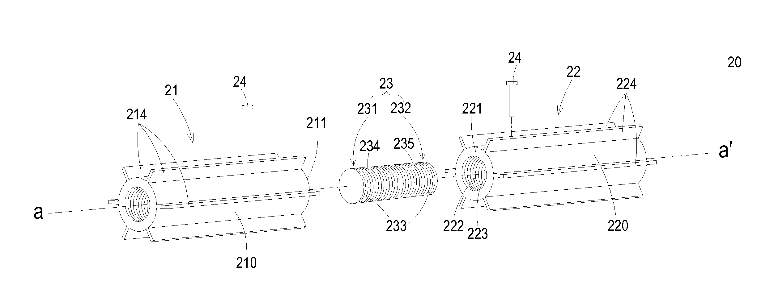
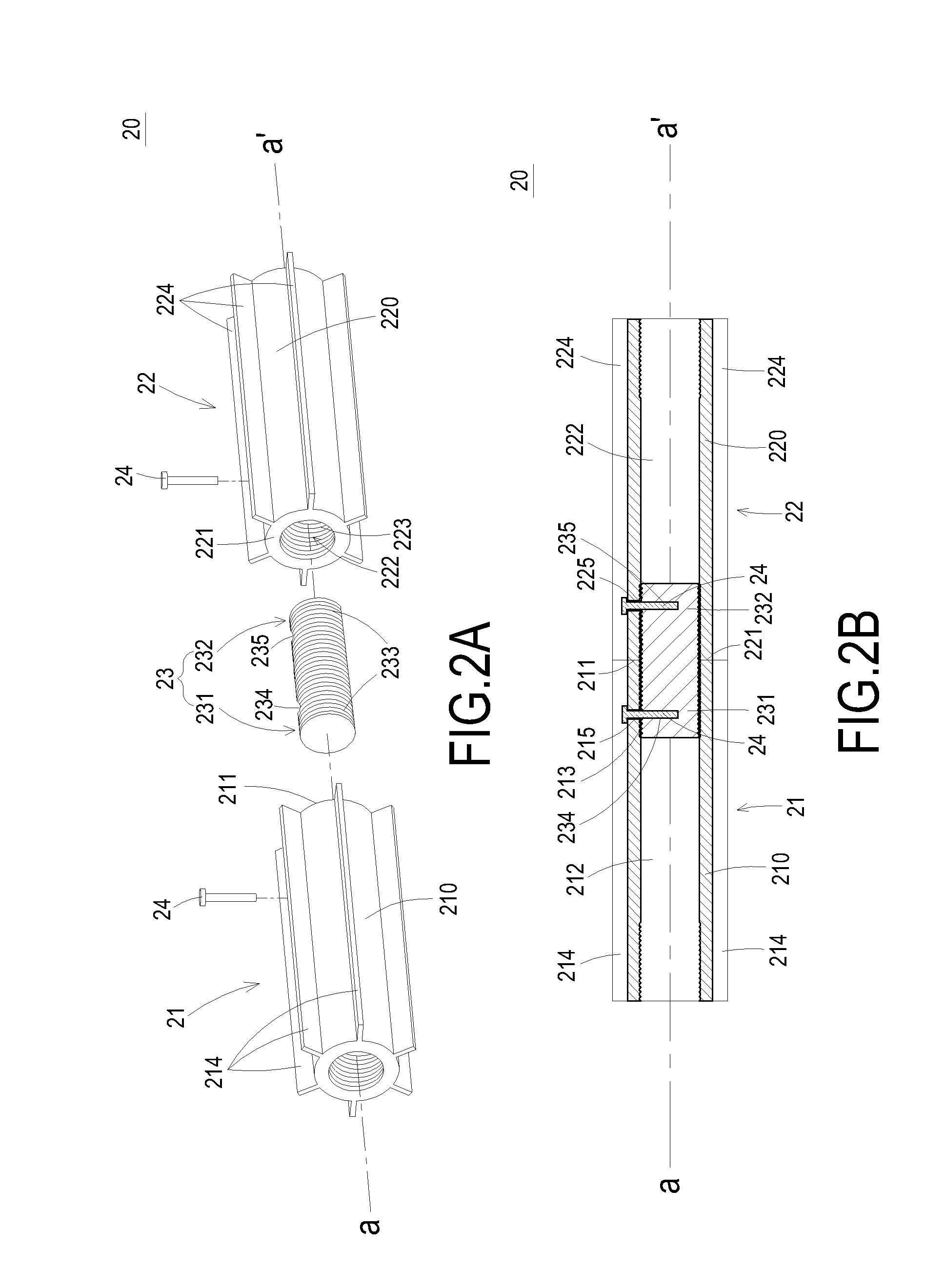
[0031]FIG. 2A is an exploded schematic diagram illustrating a preferred embodiment of a busbar assembly according to the present invention; and FIG. 2B is a composed sectional view of FIG. 2A. As shown in FIGS. 2A and 2B, a busbar assembly 20 at least includes a first metal-extruded busbar 21, a second metal-extruded busbar 22, and a connecting bar 23, which connects the first metal-extruded busbar 21 to the second metal-extruded busbar 22. The first metal-extruded busbar 21 includes a first body 210, a first accommodated space 212 and a first heat-dissipating element 214. The first body 210 has a first end-surface 211 at one end...


PUM


Abstract

A busbar assembly for conducting current is disclosed. The busbar assembly includes a first metal-extruded busbar having a first body and a first end-surface substantially vertical to an axis of the first body; a second metal-extruded busbar having a second body; and a connecting bar having a corresponding first end and a corresponding second end. The first end is buried to the first body of the first busbar and the second end extending from the first end-surface of the first metal-extruded busbar is buried to the second body of the metal-extruded busbar, whereby the first metal-extruded busbar is electrically connected to the second metal-extruded busbar through the connecting bar.

Description

FIELD OF THE INVENTION[0001]The present invention relates to a busbar assembly, and more particularly to a busbar assembly constructed of a metal-extruded busbar.BACKGROUND OF THE INVENTION[0002]Generally, the power supply system of large equipment, such as network apparatus, communication apparatus, telecommunication apparatus, uninterruptible power system (UPS), data center, uses busbar assembly to connect various electronic apparatuses for power distribution and transmission.[0003]Generally, a busbar assembly is constructed by multiple copper busbars. Please refer to FIG. 1 which is a partial view illustrating a conventional busbar assembly. As shown in FIG. 1, a conventional busbar assembly 10 at least includes a first copper busbar 11, a second copper busbar 12 and a third copper busbar 13, which are multiple bar-shaped conductive metal strips formed by directly cutting the copper plate. As shown in FIG. 1, the second copper busbar 12 is partially contacted to the first copper ...

Claims


Application Information

Patent Timeline
IPC IPC(8): H01R13/02H01R13/621
CPCH02G5/10H02G5/007
Inventor CHEN, YIN-YUANYU, CHEN-YU
Owner DELTA ELECTRONICS INC
Why Eureka
Try Eureka