
Light-emitting keyboard

a keyboard and light-emitting technology, applied in the field of keyboards, can solve the problems of increasing the complexity of the circuit design and layout, and so as to reduce the complexity of the circuit design and layout, the effect of reducing the manufacturing cost of the keyboard

Inactive Publication Date: 2009-11-19
CHICONY ELECTRONICS
View PDF10 Cites 35 Cited by
  • Summary
  • Abstract
  • Description
  • Claims
  • Application Information

AI Technical Summary

Benefits of technology

[0008]An objective of the present invention is to provide a light-emitting keyboard incorporating a scissor assembly whose lower ends are connected to a first and second fixation brackets of a supporting plate and whose upper ends are connected to the bottom of a keycap such that an elastic member of a membrane circuit board passes through a first opening of the supporting plate and the scissor assembly to engage with the bottom of said keycap. In one embodiment of the present invention, in comparison with prior arts, fewer openings or apertures may be found on the membrane circuit board of the keyboard, and this may significantly reduce the complexity of the design and layout of the circuit board as well as the manufacturing costs of the keyboard.
[0009]Another objective of the present invention is to provide a light-emitting keyboard of greater luminance. In one embodiment of the present invention, a light-emitting keyboard may be further provided with a first reflector and a second reflector to enhance the reflection and retroreflection of the light and thus the light emitting capability and efficiency of the light-emitting keyboard.
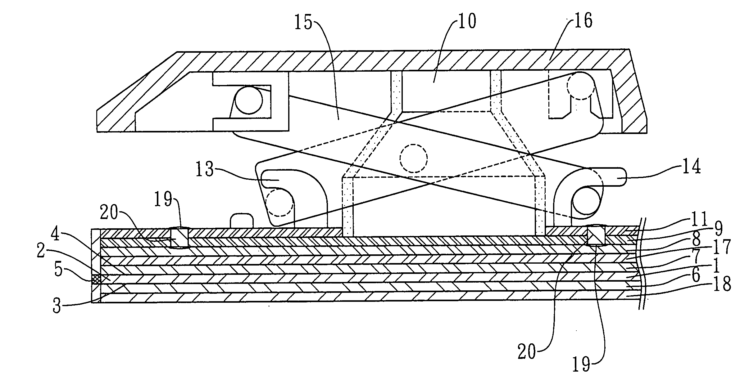
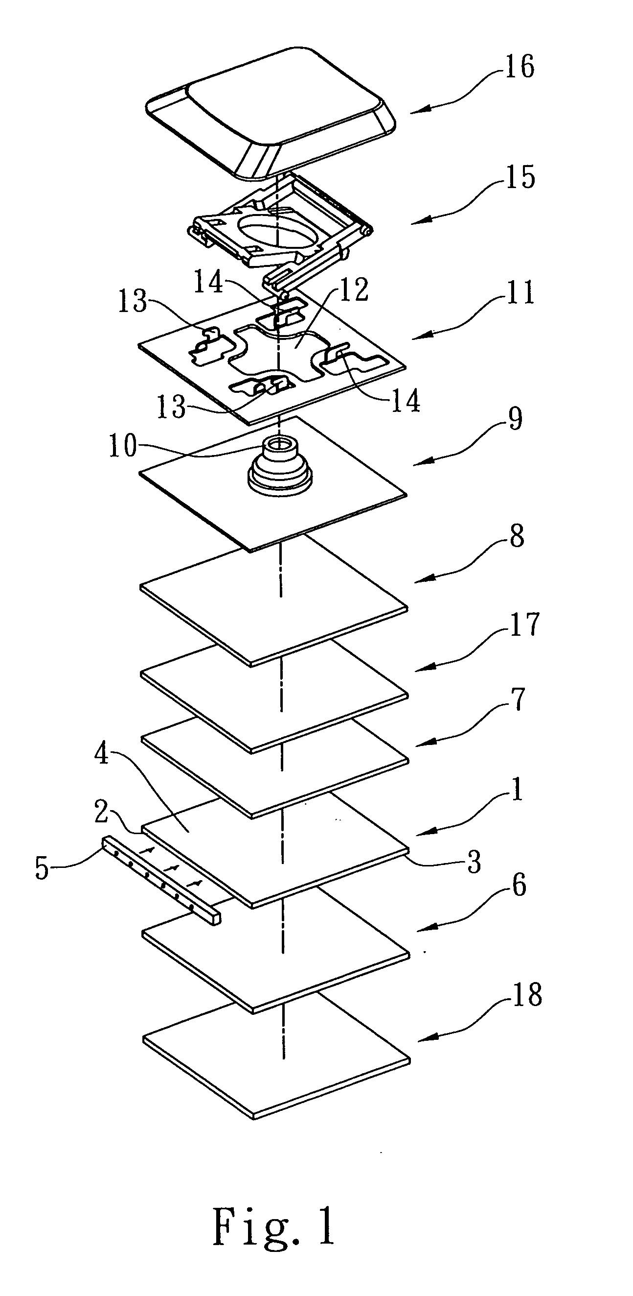
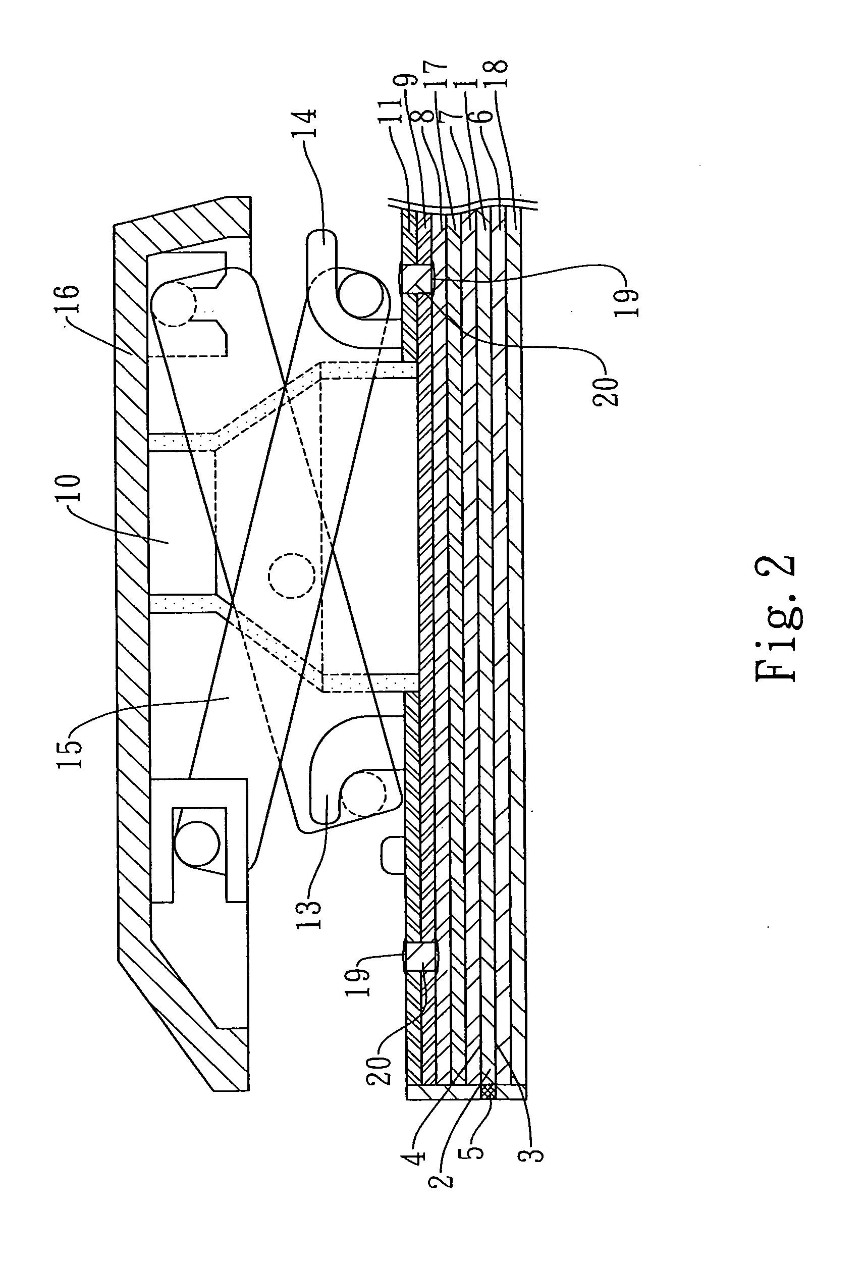
[0010]In a preferred embodiment of the present invention, a light-emitting keyboard comprises: a light guide having a light entrance surface, a bottom surface and a light exit surface; a light source provided on one side of the light entrance surface; a first reflector provided underneath the bottom surface of the light guide to prevent the light emitted by the light source from escaping from the bottom surface of the light guide by reflecting said light towards the light exist surface of the light guide; a second reflector provided on top of the light exit surface; a membrane circuit board having an elastic member provided on top of the second reflector; a supporting plate provided on top of the membrane circuit board, said supporting plate further including a first opening corresponding to the elastic member of the membrane circuit board and at least one first fixation bracket and at least one second fixation bracket adjacent to the first opening thereon; and a scissor assembly disposed on and engaged with the supporting plate to support a keycap thereon; wherein the lower ends of the scissor assembly may be engaged with the first and second fixation brackets of the supporting plate respectively and the upper ends of the scissor assembly may be received at a bottom of the keycap; and wherein the elastic member of the membrane circuit board may pass through the first opening of the supporting plate and the scissor assembly to engage with the keycap. Furthermore, in one embodiment, said second reflector may permit a portion of the light originated from the light source to penetrate therethrough in a direction towards the bottom of the keycap and reflect another portion of the light originated from the light source back towards the light exit surface of the light guide.

Problems solved by technology

Such design and structure inevitably increase the number of openings required on the membrane circuit board to allow the respective ends of all the scissor structures to pass therethrough and also unfavorably cause an increase in the complexity of the design and layout of the circuit as well as the manufacturing costs of the keyboard.

Method used


Image

  • Light-emitting keyboard
  • Light-emitting keyboard
  • Light-emitting keyboard

Examples


Embodiment Construction

[0020]The present invention will be described more fully hereinafter with reference to the accompanying drawings, in which preferred embodiments of the invention are shown. This invention may, however, be embodied in many different forms and should not be construed as limitations to the embodiments set forth herein; rather, these embodiments are provided so that this disclosure will be thorough and complete, and will fully convey the scope of the invention to those skilled in the art.

[0021]FIG. 1 and FIG. 2 representatively show an exploded view and a sectional view of a preferred embodiment of a light-emitting keyboard of the present invention. For illustration purposes, a person skilled in the art shall understand that a single key unit of the light-emitting keyboard illustrated in the drawings represents a group of similar key units on the keyboard. Modules similar to those equipped in a keyboard, such as top casing and bottom casing, are omitted for illustration purposes.

[0022]A...


PUM


Abstract

The present invention is related to a light-emitting keyboard, comprising: a light guide having a light entrance surface, a bottom surface and a light exit surface; a light source provided adjacent to the light entrance surface of the light guide; a first reflector disposed underneath the bottom surface of the light guide to reflect the light originated from the light source to enter into said light guide; a second reflector disposed on top of said light exit surface of the light guide; a membrane circuit board disposed on top of said second reflector, said membrane circuit board being provided with an elastic member; a supporting plate disposed on top of the membrane circuit board; a scissor assembly engaged with said supporting plate and provided thereon; and a keycap supported by said scissor assembly.

Description

BACKGROUND OF THE INVENTION[0001]1. Field of the Invention[0002]The present invention relates to a keyboard and in particular, to a light-emitting keyboard; said keyboard may be of lower manufacturing costs, greater luminance and effective circuit design with a more secure structure.[0003]2. Description of the Related Art[0004]With the popularity of computer, users not only pursue better computer efficiency but also pay more attention to the function and design of computer accessories such as mouse and keyboard. As computer has become an indispensable device in nearly every aspect of modern life from telecommunication, commerce, editing to graphics design, some manufacturers equip keyboard, one of the most important input devices for computer, with backlit keys so that the user can perform input tasks under inadequate lighting. Besides, the back lighting makes the keyboard look fancy.[0005]Referring to the description on a light-emitting keyboard of ROC Publication No. 509955, the k...

Claims


Application Information

Patent Timeline
Patent Type & Authority Applications(United States)
IPC IPC(8): H01H9/00
CPCG06F3/0202
Inventor CHEN, TSUNG-MINCHEN, CHUN-LINHUANG, CHENG-HSIUNGCHEN, CHIEN-SHUO
Owner CHICONY ELECTRONICS
Learn More